

Heat exchanger assembly for a gas turbine engine
A gas turbine and heat exchanger technology, applied in indirect heat exchangers, heat exchanger types, heat exchanger shells, etc., can solve problems affecting engine performance, etc.
- Summary
- Abstract
- Description
- Claims
- Application Information
AI Technical Summary
Problems solved by technology
Method used
Image

Examples
Embodiment Construction
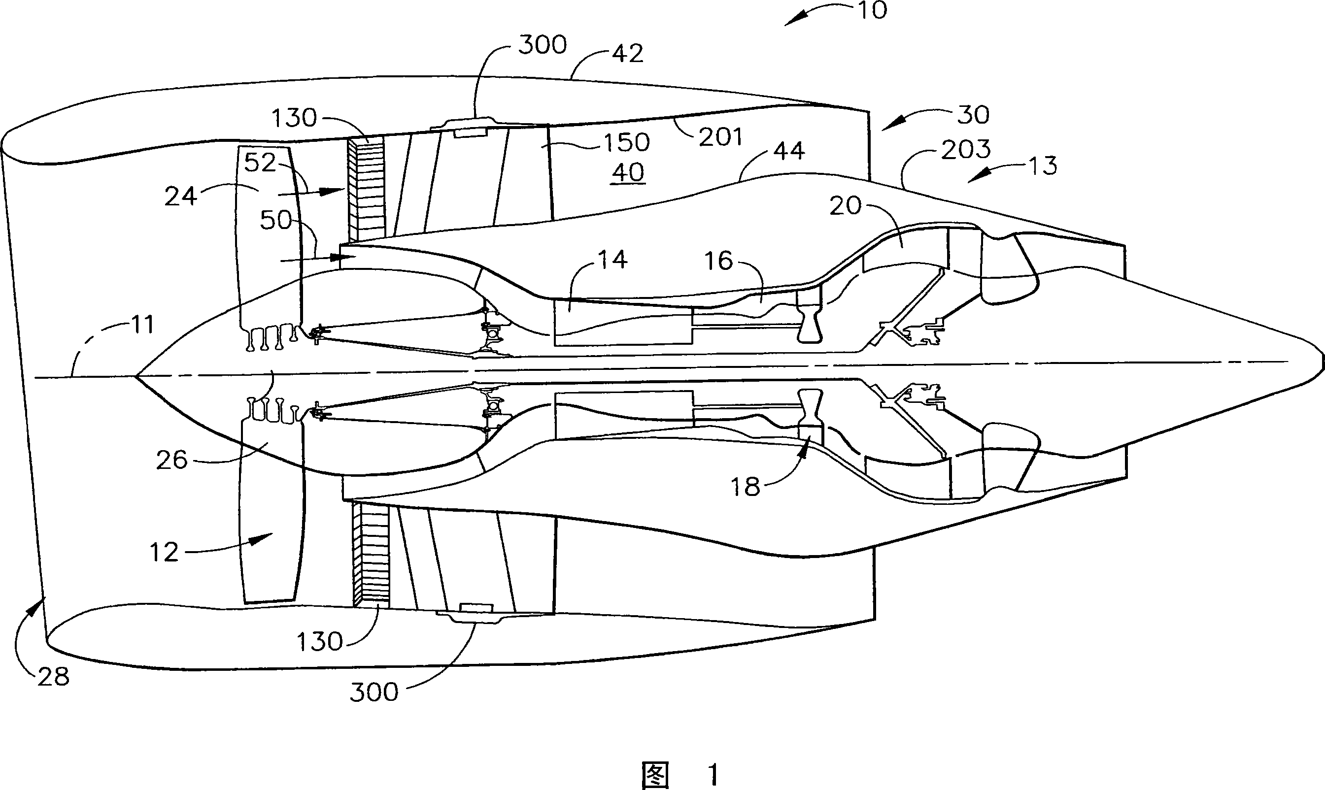
[0017] FIG. 1 is a schematic diagram illustrating an exemplary gas turbine plant 10 having a longitudinal axis 11 . The gas turbine plant 10 includes a fan plant 12 and a central gas turbine 13 . The central gas turbine includes a high pressure compressor 14 , a combustor 16 , and a high pressure turbine 18 . In the example embodiment, the gas turbine plant 10 may also include a low pressure turbine 20 . The fan assembly 12 includes a series of fan blades 24 extending radially outward from a rotor disk 26 . Engine 10 has an inlet side 28 and an outlet side 30 . Gas turbine assembly 10 also includes a series of bearing assemblies (not shown in FIG. 1 ) that provide rotational and axial support for, for example, fan assembly 12 , compressor 14 , high pressure turbine 18 , and low pressure turbine 20 .
[0018] In operation, air flows through the fan assembly 12 and a first portion 50 of the airflow is directed through the compressor 14 where it is further compressed and input...
PUM
 Abstract
Description
Claims
Application Information