Method and device of quick-speed mechanism for object to be paid

A fast and support mechanism technology, applied in the direction of coin-operated equipment for distributing discrete items, coin-operated equipment for distributing discrete items, coin-operated equipment for distributing discrete items, etc., can solve the problem of slow transactions and payment Long time, chaotic seal management and other problems, to achieve the effect of improving work efficiency

Inactive Publication Date: 2008-05-14
BEIJING RINRONG TECH
View PDF0 Cites 12 Cited by
  • Summary
  • Abstract
  • Description
  • Claims
  • Application Information

AI Technical Summary

Problems solved by technology

[0002] The current automatic teller machines, automatic card vending machines, automatic vending machines, and automatic ticke

Method used


Image

  • Method and device of quick-speed mechanism for object to be paid
  • Method and device of quick-speed mechanism for object to be paid
  • Method and device of quick-speed mechanism for object to be paid

Examples


example 1

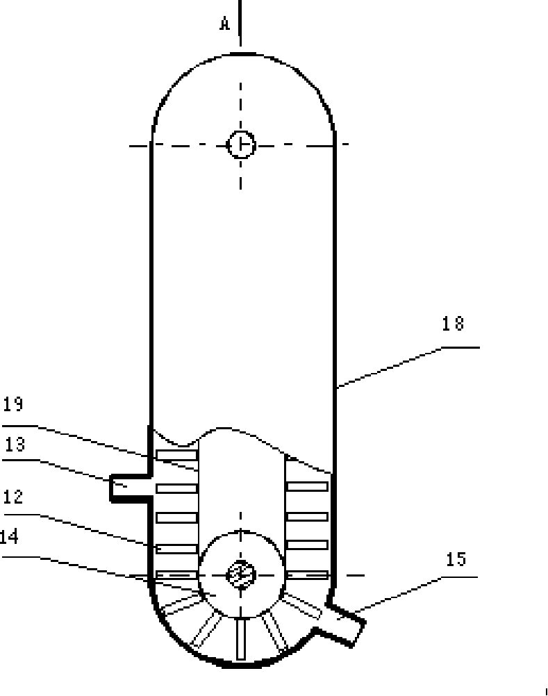
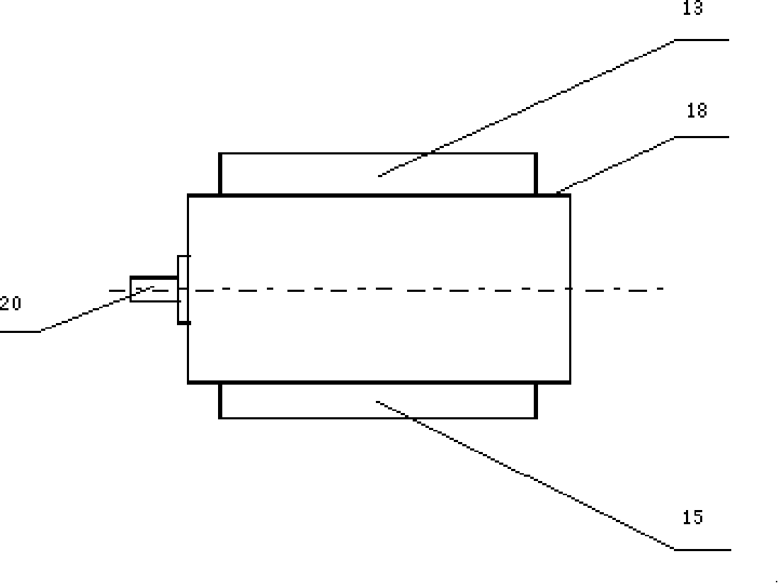
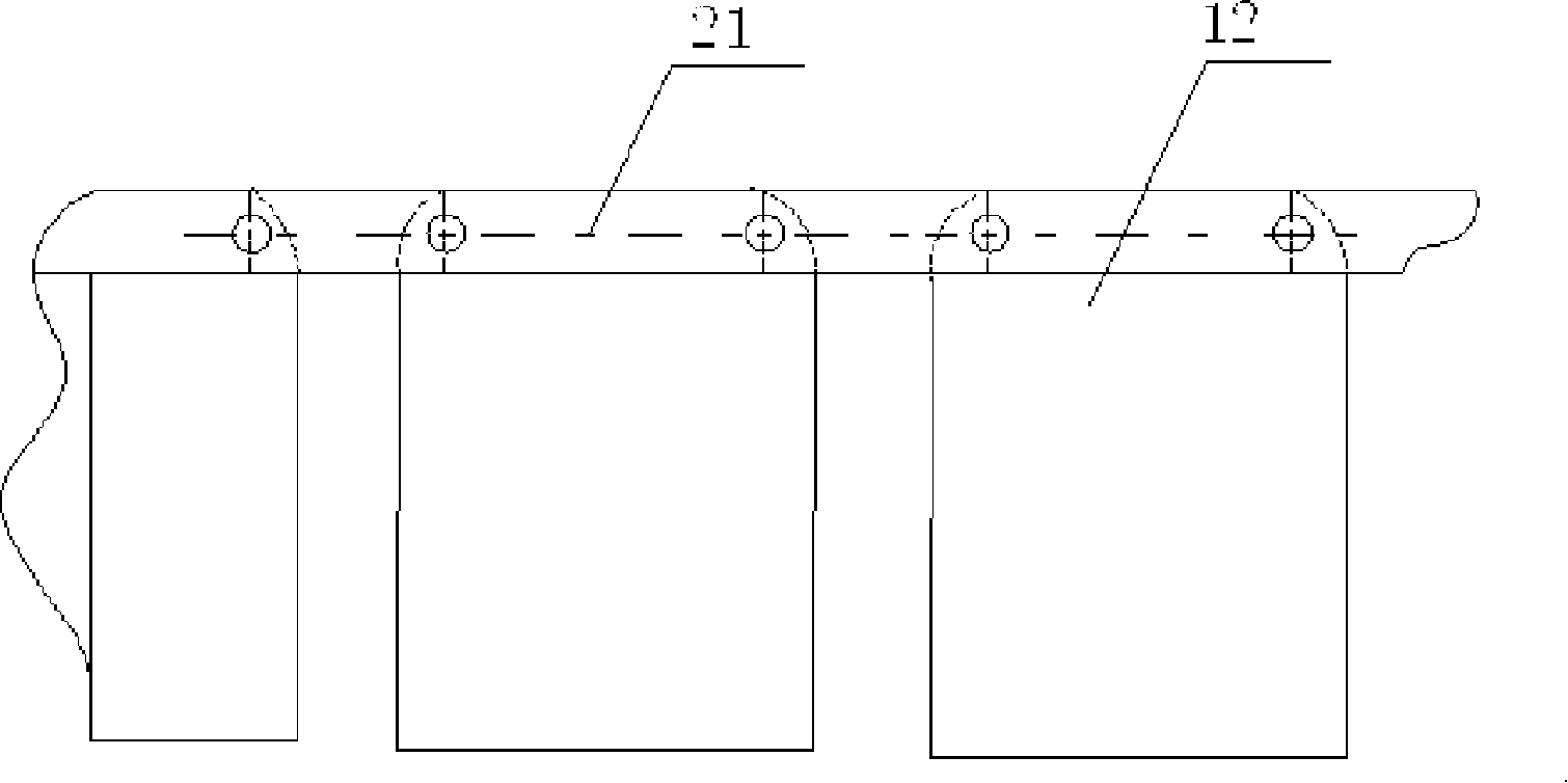
[0029] Example 1: see figure 1 , figure 2 , image 3 , Figure 4 , it is made up of storage unit 12, cash into inlet 13, sprocket wheel 14, outlet 15 equipped with photoelectric sensor, housing 18, chain or belt 19, stepper motor 20. The storage unit 12 is connected on the outer chain plate 21 of the chain or the outside of the belt, and the storage unit is a rectangular box with an outer opening. The housing is covered on the outside of the drive chain and the storage unit. The housing is provided with a banknote insertion port 13, and the lower right corner of the housing is provided with an outlet 15 of cash bundles. The axles of two sprocket wheels 14 are supported on the housing. Start the stepping motor, drive the chain or belt to rotate through the sprocket, and the storage unit on the chain or belt rotates with the chain or belt; when the storage unit turns to the exit of the bundle of cash, it will be discharged, and when it passes the photoelectric sensor at the ...

example 2

[0030] Example 2: if Figure 5 , Figure 6 , Figure 7 The shown negative payment device is composed of a cash insertion port 1, a runner body 2, a cash storage unit 3, a photoelectric sensor 4, a cash outlet 5, a gear 6, a push rod 7, a casing 8, and a support 9. The main body of the rotating wheel is controlled by a stepping motor to rotate, and the main body of the rotating wheel is provided with several cash storage units whose opening direction is at an angle a to the radial direction. The push-out rod is on the same level as the banknote outlet and is on the inner side of the wheel. The push-out rod can push out any bundle of cash in the storage unit that is turned to this position. A photoelectric sensor is installed on the passage of the banknote outlet. When the bundle of cash passes through the When the banknote exit channel, the photoelectric sensor sends a signal to the computer, and the computer compares the number of bundles of banknotes actually paid with the ...

example 3

[0031] Example 3: figure 2 As shown, the payment device consists of a cash inlet 1, a wheel body 2, a cash storage unit 3, a photoelectric sensor 4, a cash outlet 5, an electromagnet 6, a push rod 7, a protective cover 8, a support 9, and a lever 10 compositions. The push-out rod is driven by the electromagnet to push the bundle of cash out of the storage unit. Others are the same as example 12.


PUM


Abstract

The invention relates to a delivering mechanism which can be used on an automatic teller machine, an automatic card selling machine, an automatic goods selling machine and an automatic ticket selling machine. The invention solves the problem that the existing automatic teller machine, automatic card selling machine, automatic goods selling machine and automatic ticket selling machine take long time to deliver and are slow in transaction. A delivering mechanism is arranged inside a box with an inlet and an outlet; the delivering mechanism comprises a plurality of storage units which are arranged together in parallel and are movable; the currency is identified and put into the storage unit of the delivering mechanism according to the amount; similarly, a certain amount of cards, tickets and goods are put into the delivering mechanism and the amounts are recorded in each storage unit; the currency amount planned to be delivered is entered into the computer; similarly, the amounts of cards, tickets and goods planned to be delivered are entered into the computer which controls the mechanism; the delivering mechanism is started by the computer and operates according to the orders of the computer; when the storage unit with the same amount of objects to be delivered corresponds to the outlet of the box, the objects to be delivered are discharged through the outlet.

Description

Technical field: [0001] The invention relates to a waiting-to-pay mechanism, which can be used for automatic teller machines, automatic card vending machines, automatic vending machines, automatic ticket vending machines, and small-batch item management, such as seals and books. Background technique: [0002] The current automatic teller machines, automatic card vending machines, automatic vending machines, and automatic ticket vending machines take a long time to pay, relatively slow transactions, and chaotic seal management. Invention content: [0003] The object of the present invention is to solve the above-mentioned problems. The scheme that the present invention solves its technical problem adopts is: [0004] 1. Install the to-be-paid mechanism in the box with the entrance and exit; [0005] 2. The institution to be paid consists of several storage units; [0006] 3. The storage units are arranged side by side and are movable; [0007] 4. Sort cash according to ...

Claims


Application Information

Patent Timeline
IPC IPC(8): G07F19/00G07F11/00G07D13/00B65G17/12B65G29/00B65G47/34B65G47/74
Inventor 陆洪瑞
Owner BEIJING RINRONG TECH
Why Eureka
Try Eureka