Encapsulated medical device

A technology of medical devices and capsules, which is applied in the field of capsule medical devices, and can solve the problems of undisclosed capsules and undisclosed methods for detecting the direction of capsules or capsule antennas

Active Publication Date: 2008-05-14
OLYMPUS CORP
View PDF4 Cites 17 Cited by
  • Summary
  • Abstract
  • Description
  • Claims
  • Application Information

AI Technical Summary

Problems solved by technology

[0007] However, Japanese Patent Application Laid-Open No. 2003-135389 does not disclose a method for specifically detecting the position of the capsule. In addition, it does not disclose a method for detecting the direction of the capsule or the antenna in the capsule based on a wirelessly transmitted signal.

Method used


Image

  • Encapsulated medical device
  • Encapsulated medical device
  • Encapsulated medical device

Examples


no. 1 approach

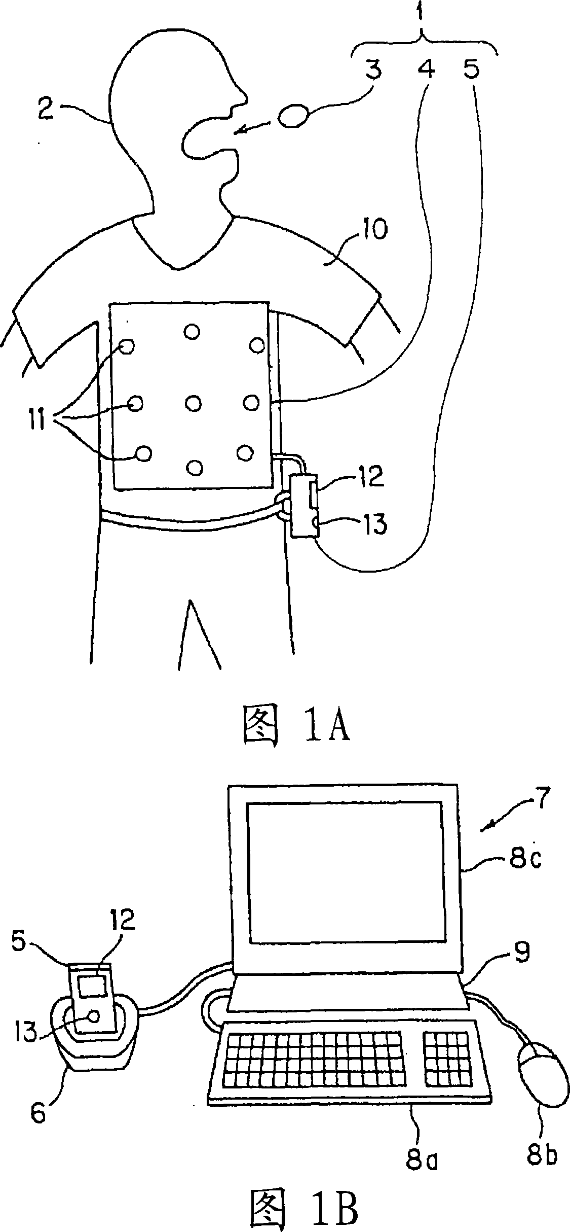
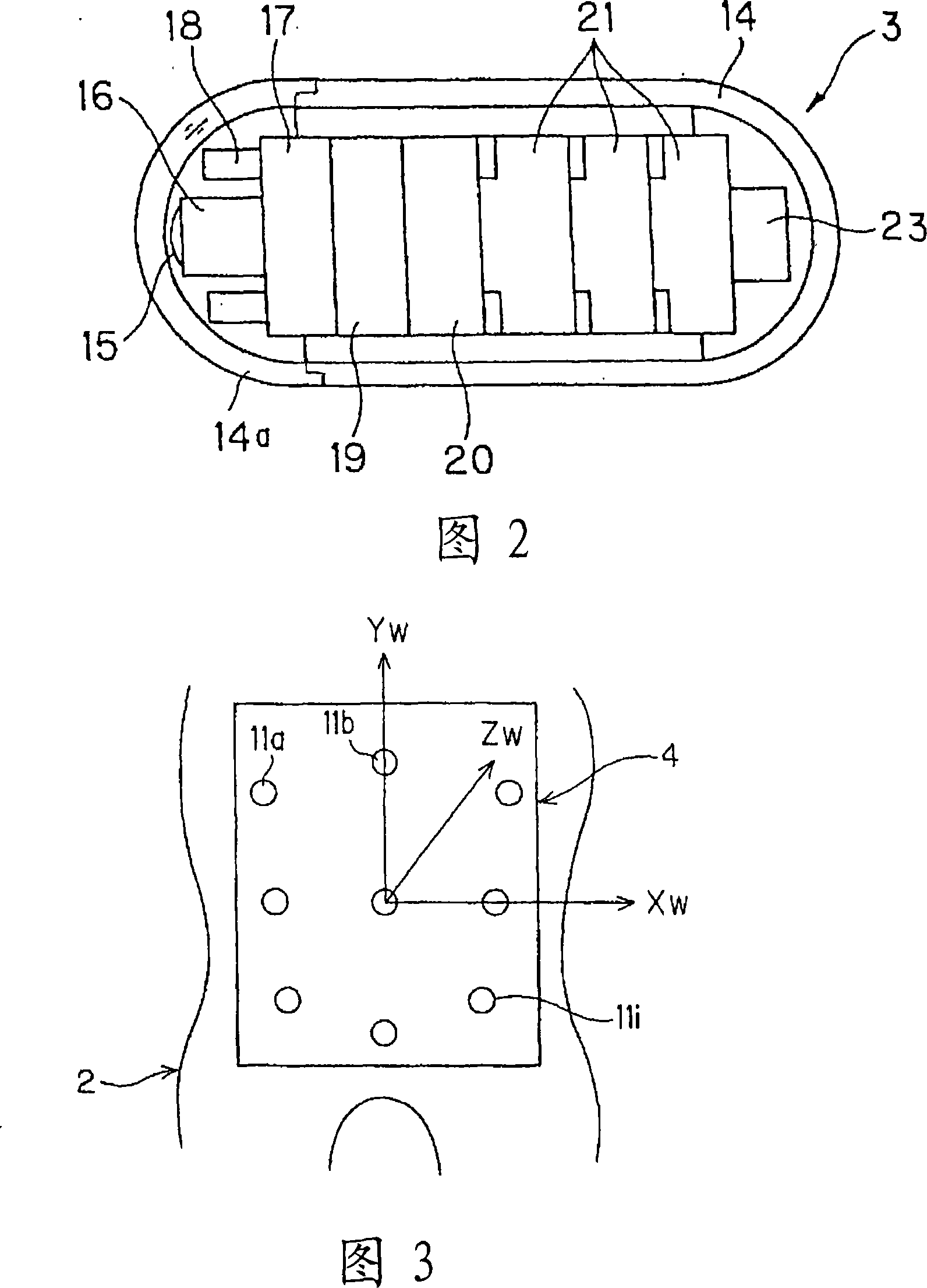
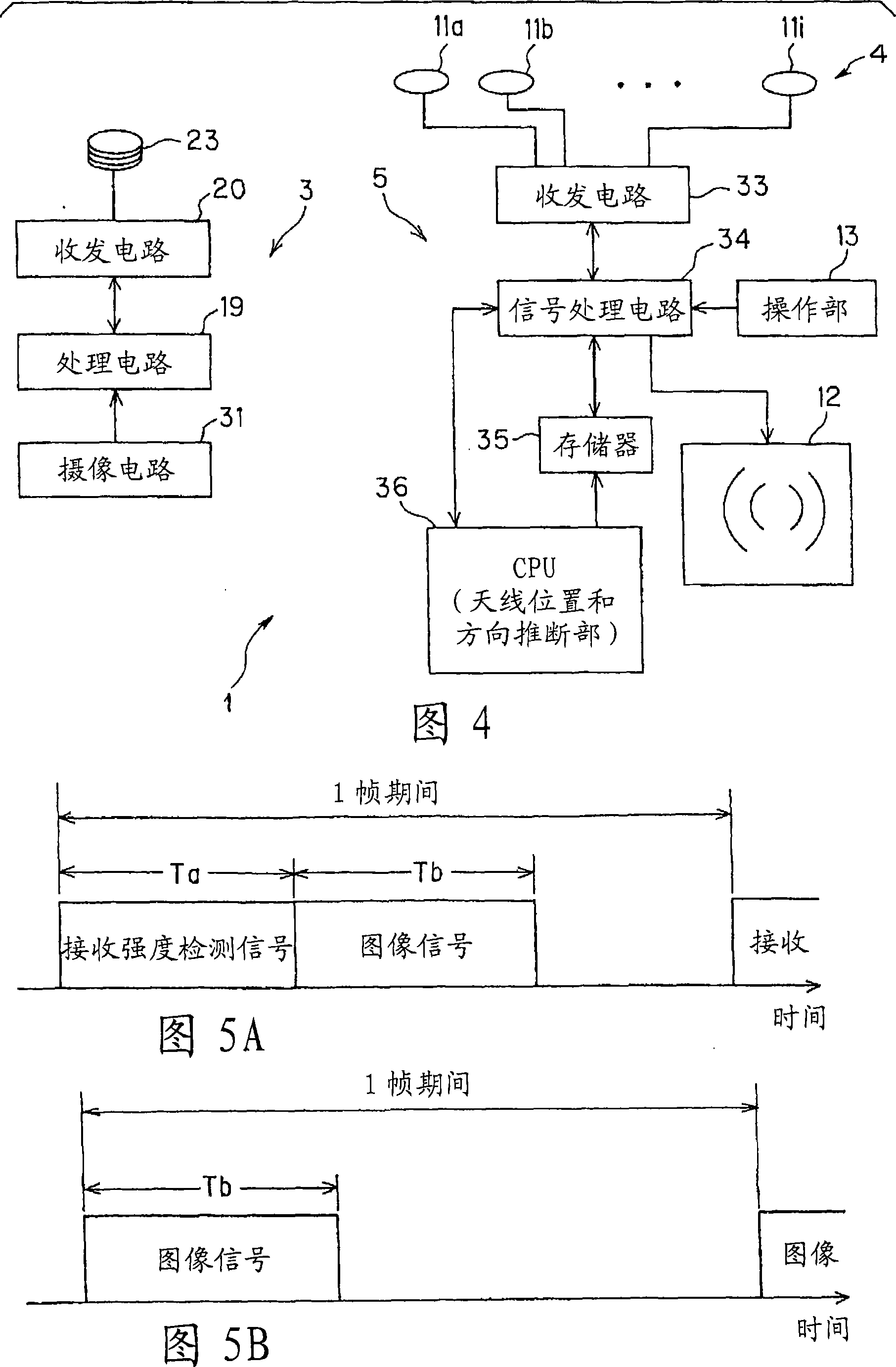
[0032] 1 to 11 are diagrams of a first embodiment of the present invention. FIG. 1A is a diagram showing an example of main parts of the capsule medical device according to the first embodiment of the present invention. FIG. 1B is a diagram showing a state in which the external device of FIG. 1A is connected to a terminal device via a cradle. Fig. 2 is a diagram showing the internal structure of the capsule endoscope. FIG. 3 is a diagram showing an arrangement example of a plurality of antennas constituting the antenna unit and a coordinate system set for the antennas. Fig. 4 is a block diagram showing a schematic internal configuration of the capsule endoscope device in Fig. 1A.

[0033] FIG. 5A is a diagram showing an example of signals transmitted from the capsule endoscope in FIG. 1 in one frame period. FIG. 5B is a diagram showing an example of a signal transmitted from the capsule endoscope in FIG. 1 in one frame period, which is different from FIG. 5A . FIG. 6 is a ...

no. 2 approach

[0168] Next, a second embodiment of the present invention will be described. The hardware configuration of this embodiment is the same as that of the first embodiment. The present embodiment is an embodiment in which an electric field that takes into consideration the effect when the distance between the capsule endoscope 3 and the antenna 11 s attached to the body surface of the patient 2 is further considered in the first embodiment is used.

[0169] The operation of this embodiment will be described below.

[0170] The frequency of the electromagnetic field generated by the antenna 23 disposed in the capsule endoscope 3 is high, and as shown in FIG. 1A, the distance between the capsule endoscope 3 and the antenna 11s installed on the body surface of the patient 2 is sufficiently far In the case of , the radiation electromagnetic field component of the electromagnetic field reaching the antenna 11s becomes the largest. However, if the distance between the capsule endoscope...

no. 3 approach

[0195] A third embodiment of the present invention will be described with reference to FIG. 12 . First, the structure of this embodiment will be described. The configuration of the capsule endoscope device according to the present embodiment is different from the configuration (shape) of the antenna 11 used in the antenna unit 4 in the first embodiment.

[0196] And, therefore, the expression of the electric field detected by the antenna 11 is different. Specifically, as the antenna 11 used in the present embodiment, a divided circular antenna (non-closed circular antenna) 11 as shown in FIG. 12 is used. Other structures are the same as those of the first embodiment.

[0197] Next, the operation of this embodiment will be described.


PUM


Abstract

The invention provides an encapsulated medical device capable of accurately detecting a position where biological information is acquired by imaging in the biological body and the like. A circular loop antenna (23) built in an encapsulated endoscope (3) moving in the living body transmits a high-frequency signal, which is received by a plurality of antennas (11a to 11i) arranged on the living body surface. A CPU (36) sets the position and the direction of the initial state of the antenna (23) and performs estimation of the position and the direction so as to calculate newly estimated position and direction and update the position and the direction of the initial state. For the updated position and the direction, the estimation is performed similarly. This processing is repeated until the shift amount of the position updated by the estimation becomes sufficiently small. This enables an accurate position estimation.

Description

technical field [0001] The present invention relates to a capsule medical device inserted into a living body to perform imaging and the like. Background technique [0002] Endoscopes capable of diagnosing the inside of the body cavity or performing treatment as necessary by inserting an insertion portion into the body cavity have been widely used in the medical field and the like. [0003] In addition, recently, a capsule-shaped medical device in the form of a capsule, which can image the inside of a body cavity by swallowing it through the mouth and perform endoscopic inspection, is also being put into practical use. [0004] When inserted into a body cavity, the capsule medical device usually moves in the body cavity by peristaltic motion or the like. Therefore, the user may wish to know which position in the body cavity the information obtained by the capsule medical device corresponds to. [0005] Therefore, for example, Japanese Patent Application Laid-Open No. 2003-1...

Claims


Application Information

Patent Timeline
Patent Type & Authority Applications(China)
IPC IPC(8): A61B1/00G01S5/02A61B5/06
CPCA61B5/07A61B1/00016A61B1/041A61B5/06G01S5/0252A61B5/6805A61B1/0005G01S5/02A61B2560/0456A61B5/062G01S5/02527G01S5/02522A61B1/00055A61B5/073G01S5/017
Inventor 长谷川润野波徹绪
Owner OLYMPUS CORP
Why Eureka
Try Eureka