Glucose sensor

A technology of glucose concentration, living body, applied in the field of non-invasive measurement of blood glucose concentration

Inactive Publication Date: 2008-05-14
KONINKLIJKE PHILIPS ELECTRONICS NV
View PDF0 Cites 11 Cited by
  • Summary
  • Abstract
  • Description
  • Claims
  • Application Information

AI Technical Summary

Problems solved by technology

However, the problem of determining blood flow rate now be...

Method used


Image

  • Glucose sensor
  • Glucose sensor

Examples


Embodiment Construction

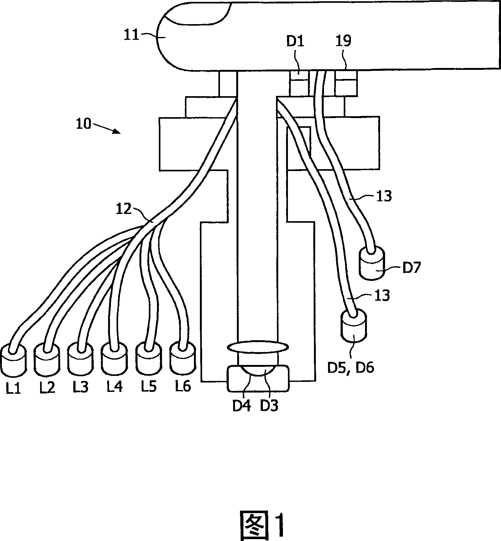
[0023] Referring to Figure 1 of the drawings, there is schematically shown a system 10 for performing non-invasive measurements of blood glucose concentration in a living being. The temperature of the fingertip surface 11 can be measured using thermistors D1 and D4 and thermopile D3 to determine the amount of heat generated. Light-emitting diodes (LEDs) L1-L6 and photodiodes D5-D7 are used to measure Hb and HbO by spectral reflectance spectroscopy 2 Concentration, however, Raman spectroscopy, photoacoustic spectroscopy, thermal emission spectroscopy and optical coherence tomography may also be used.

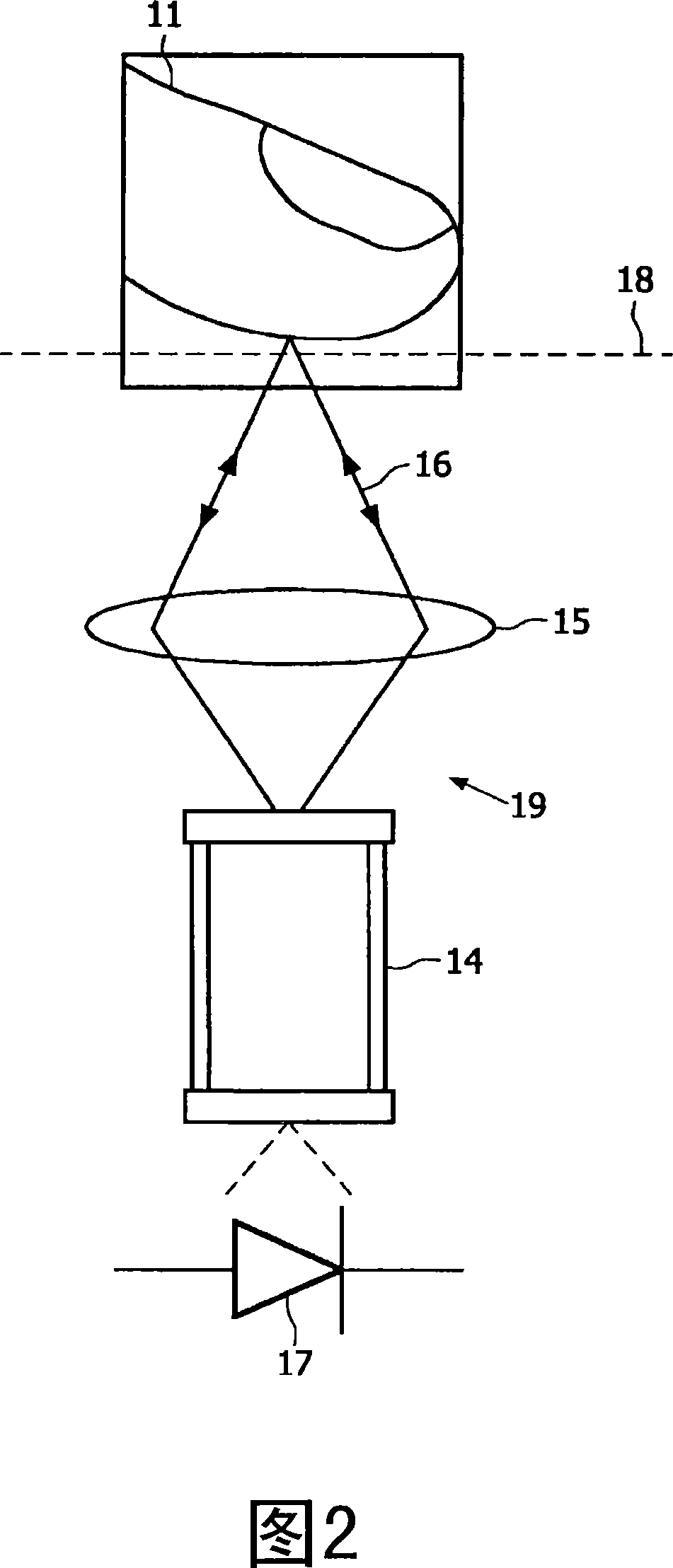
[0024] The light generated by the LEDs L1-L6 is transmitted to the surface of the finger 11 through a set of optical fibers 12, and the light reflected from the surface of the finger is returned to the photodiodes D5-D7 through a second set of optical fibers 13. For determination of Hb and HbO 2 The wavelength of the concentrated light is generally in the range of 470nm-950nm i...


PUM


Abstract

A system for the non- invasive measurement of glucose concentration in a live subject is disclosed. The system exploits the metabolic heat conformation method, and comprises temperature sensing means for measuring the body heat in respect of the subject and means for measuring the concentration of haemoglobin and oxygenated haemoglobin in the blood of the subject. The system further comprises irradiating means for irradiating a portion of the live subject, a detector for collecting the measuring beam reflected by the live subject, means for determining from the reflected measuring beam, the blood flow velocity in respect of the live subject, and means for determining glucose concentration in the live subject as a function of the body heat, the haemoglobin and oxygenated haemoglobin concentrations and the blood flow velocity.

Description

technical field [0001] The present invention relates to the non-invasive measurement of the glucose concentration in a living body, and more particularly to the non-invasive measurement of the blood glucose concentration using the so-called metabolic heat integration method. Background technique [0002] The non-invasive determination of blood glucose concentration using the well-known metabolic heat integration (MHC) method relies on the measurement of the oxidative metabolism of glucose from which the blood glucose concentration can be deduced. Body heat generated by glucose oxidation is based on a precise balance of capillary blood glucose and oxygen supply to tissue cells. The MHC method uses this relationship to estimate blood glucose by measuring body heat and oxygen supply. This relationship can be expressed by the following equation: [0003] [glucose concentration] = function [heat generated, blood flow rate, Hb, HbO 2 ] Among them, Hb and HbO 2 denote the conce...

Claims


Application Information

Patent Timeline
IPC IPC(8): A61B5/00
CPCA61B5/1455A61B5/6838A61B5/14532A61B5/6826
Inventor M·范赫佩恩M·巴利斯特雷里C·普雷苏勒
Owner KONINKLIJKE PHILIPS ELECTRONICS NV
Why Eureka
Try Eureka