Welding joint method of glass optical fibre with different component

A technology of glass optical fiber and optical fiber, which is applied in the coupling direction of optical waveguide, etc., can solve the problems of large loss of optical fiber joints, failure to meet the requirements of use, low strength, etc., and achieve the effect of large tuning range

Inactive Publication Date: 2008-05-21
SOUTH CHINA UNIV OF TECH
View PDF2 Cites 10 Cited by
  • Summary
  • Abstract
  • Description
  • Claims
  • Application Information

AI Technical Summary

Problems solved by technology

However, the emergence of new multi-component glass optical fibers and devices also brings a problem: how to connect multi-component glass optical fibers and devices to the existing network composed of standard silica glass optical fibers into a huge fiber optic network)? That is, how to realize the connection and coupling between multi-component glass optical fibers and silica optical fibers (that is, glass optical fibers with different thermal melting properties) is the last key and restrictive factor for the practical application of multi-component glass optical fibers.
This method can realize fusion splicing of multi-component glass optical fiber and silica optical fiber. However, due to the large difference in melting temperature between multi-component glass optical fiber and silica optical fiber, when the low-melting point multi-component glass optical fiber is melted, the quartz glass optical fiber basically does not change. , so the optical fiber joints fused using this asymmetric method have a large loss and very low strength, which cannot meet the requirements of use

Method used


Image

  • Welding joint method of glass optical fibre with different component
  • Welding joint method of glass optical fibre with different component

Examples


Embodiment Construction

[0013] Take, but not limited to, the fusion splice between a low melting temperature phosphate glass fiber and a standard silica glass fiber. The thermal performance parameters of phosphate glass fiber and silica fiber are shown in Table 1.

[0014] Table 1

[0015] Glass

Phosphate

quartz

Refractive index (n d )

Transition temperature (°C)

Softening temperature (℃)

Coefficient of thermal expansion (×10 7 / °C)

Single-mode fiber core diameter (μm)

1.5~1.8

350~600

450~700

65~140

5~7

1.45~1.48

1000~1200

1600~1750

5.0~5.8

8~10

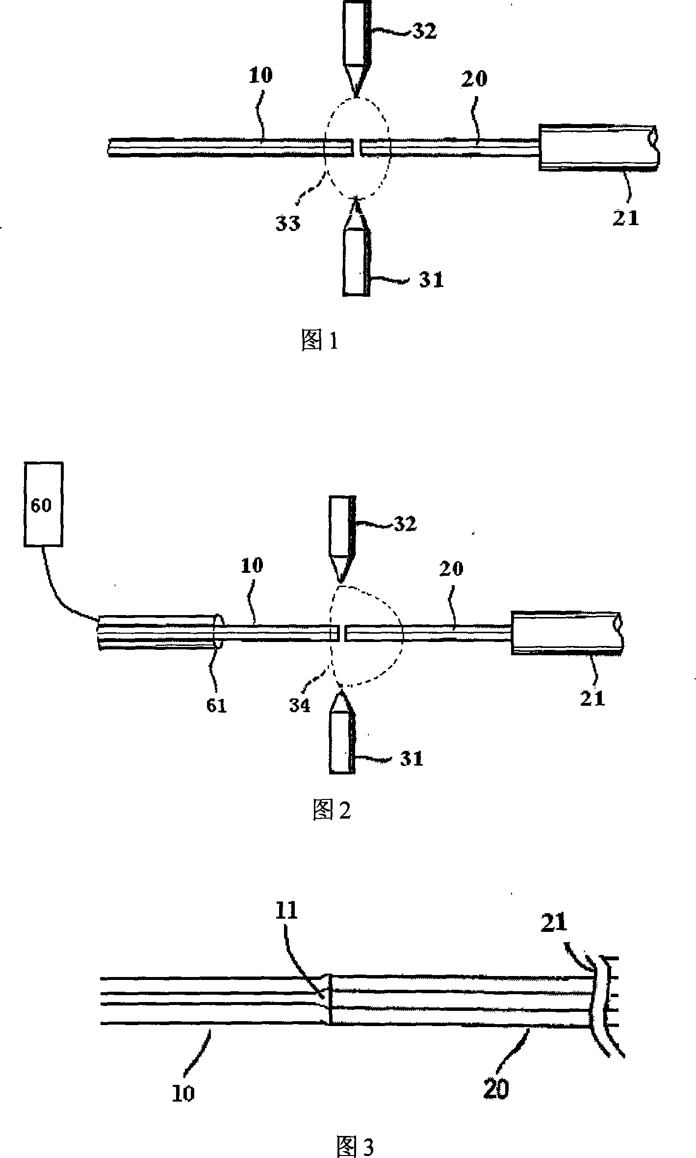
[0016] According to the present invention, an arc blowing heating structure is used to fuse two optical fibers, as shown in FIG. 2 . The quartz optical fiber 21 and the phosphate glass optical fiber 10 with the coating layer stripped are carefully placed in the V-shaped groove of the fusion splicer, and the clamp moving device a...


PUM

PropertyMeasurementUnit
melting pointaaaaaaaaaa
softening pointaaaaaaaaaa

Abstract

The present invention discloses a fusion welding method for glass fiber with different components. Air flow is used for vertically blowing discharge arc to form a temperature gradient field. So optical fibers with different hot melting properties are melted at the same time and the permanent connection is realized. Two optical fibers are placed symmetrically between a pair of discharge electrodes. The optical fiber with low melting temperature is placed in a vent pipe or the vent pipe is placed parallel to the optical fiber with low melting temperature. Through air blowing arc, the size of the air flow is adjusted and the suitable temperature gradient field is obtained. The temperature field is capable of resulting in that the optical fibers with different melting temperatures placed at the two sides of the electrode show the melting state at the same time. A connecting joint with low loss and high intension is formed after the optical fibers being contacted. The present invention has the advantages that the tunable range is big and the optical fibers with different thermal properties which can not be fusion jointed by the traditional method can be fusion jointed by the present invention.

Description

technical field [0001] The invention relates to a fusion splicing method of glass optical fibers, in particular to a fusion splicing method of glass optical fibers with different components. Background technique [0002] Multicomponent glass optical fibers and devices with excellent performance are of great significance for improving the performance of next-generation all-optical networks, and also help to realize the miniaturization, integration, high performance and multifunctionalization of optoelectronic devices. However, the emergence of new multi-component glass optical fibers and devices also brings a problem: how to connect multi-component glass optical fibers and devices to the existing network composed of standard silica glass optical fibers into a huge fiber optic network)? That is, how to realize the connection and coupling between multi-component glass optical fibers and silica optical fibers (that is, glass optical fibers with different thermal melting propert...

Claims


Application Information

Patent Timeline
Patent Type & Authority Applications(China)
IPC IPC(8): G02B6/255
Inventor 杨中民杨昌盛徐善辉
Owner SOUTH CHINA UNIV OF TECH
Why Eureka
Try Eureka