Intracorporeal indwelling equipment

A component and membrane-like technology, applied in the field of indwelling devices in the body, can solve problems such as irritation of the stomach wall, difficulty in inserting the patient's fistula, and ulceration

Inactive Publication Date: 2008-05-21
科文迪安有限公司
View PDF1 Cites 10 Cited by
  • Summary
  • Abstract
  • Description
  • Claims
  • Application Information

AI Technical Summary

Problems solved by technology

However, with the aforementioned conventional indwelling devices in the body, since the inner holding member extends in a direction perpendicular to the cylindrical member, it is difficult to insert or remove from the patient's fistula.
Also, since the inner holding member is formed in a flat flange-like shape, the corners of the inner holding member irritate the stomach wall, which can produce ulcers

Method used


Image

  • Intracorporeal indwelling equipment
  • Intracorporeal indwelling equipment
  • Intracorporeal indwelling equipment

Examples


Embodiment 1

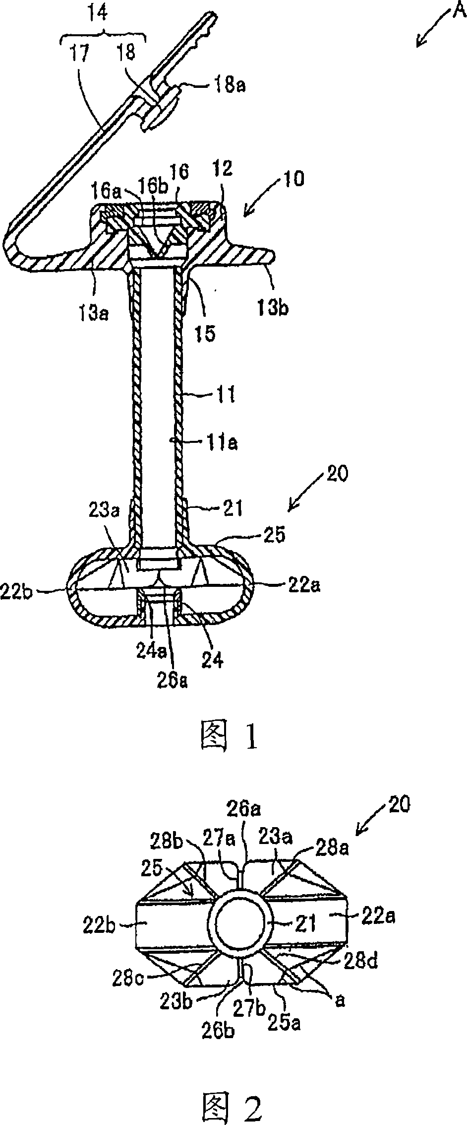
[0037] Hereinafter, a description will be given about a first embodiment of the present invention. Fig. 1 shows an indwelling device A in the body of this embodiment. This indwelling device A in the body is set in a fistula formed between the patient's abdomen and the stomach wall for feeding fluid such as liquid food or the like into the stomach. The indwelling device A in the body consists of an outer holding member 10, a cylindrical member 11 connected to the lower end of the outer holding member 10, and an inner holding member 20 connected to the lower end of the cylindrical member 11, all of which are made of polyurethane. Hereinafter, description will be made for the case where the outer holding member 10 is on the upper side and the inner holding member 20 is on the lower side.

[0038] The outer holding member 10 consists of a main body 12 formed in a rather thick ring shape, a pair of outer holding pieces 13a, 13b protruding outward from left / right lower end portions...

Embodiment 2

[0068] Fig. 12 is a diagram illustrating an indwelling device B in the body in a second embodiment of the present invention. 13-15 illustrate the inner retaining member 40 of the indwelling device B in the body. The inner holding member 40 is composed of a cylindrical connecting portion 41 , four belt-like members 42 a , 42 b , 42 c , 42 d , four film-like members 43 a , 43 b , 43 c , 43 d , and a connecting member 44 . The connecting portion 41 has the same structure as the connecting portion 21 of the indwelling device A in the body. The belt members 42 a , 42 b , 42 c , 42 d are connected to the lower end outer peripheral surface of the connecting portion 41 . They extend outward from the outer peripheral surface of the connecting portion 41 to four sides, and then bend, which form a curved shape as extending from the lower side to the right, and are below the connecting portion 41 .

[0069] That is, the lower end portions of the belt-like members 42 a and the like are g...

Embodiment 3

[0075]Fig. 17 is a top view of the inner holding member 50 with an indwelling device in the body according to the third embodiment of the present invention. The inner holding member 50 is composed of narrow (thin) belt-like members 52a, 52c as portions corresponding to the belt-like members 42a, 42c on the inner holding member 40 shown in FIG. 13 . Other features of the structure of the indwelling device in the body having the inner holding member 50 are the same as those in the indwelling device B in the body. Therefore, using the same part numbers as in the foregoing, they will not be described again. In this case, when the inner holding member 50 is stretched, its shape in plan view becomes a shape as shown in FIG. 18 . In this case, insertion and withdrawal of the indwelling device in the body can also be easily performed.

[0076] The present invention is not limited to the foregoing embodiments. The present invention can also be appropriately modified. For example, i...


PUM


Abstract

The present invention provides an intracorporeal indwelling equipment having an internal holding member to be set in the stomach. Said internal holding member is composed of flexible ribbon-shaped members and flexible membrane-like members that are set on the portions of ribbon-shaped member, forming a dome-shaped portion. In the center of the outer periphery of membrane-like member, a notch and folding creases are formed to assist in deployment and help prevent the generation of ulcers and buried bumper syndrome.

Description

technical field [0001] The present invention relates to an indwelling device for administering fluid, such as liquid food, into a patient's stomach or other designated location, or for removing urine or other fluid waste from a patient's renal pelvis or other designated location in the body. excreted from the site. Background technique [0002] In the prior art, for people who cannot eat by mouth due to old age or disease (hereinafter referred to as patients), indwelling devices in the body are used to feed liquid food, nutrients or other fluids. The indwelling device in the body consists of the following parts: a cylindrical member inserted into a fistula provided in the patient's body for ingesting liquid food; an inner holding member attached to the end of the cylindrical member and inserted into the stomach wall of the patient; and a cylindrical member attached to the An outer holding member on the outer peripheral surface of the member and provided on the skin surface ...

Claims


Application Information

Patent Timeline
Patent Type & Authority Applications(China)
IPC IPC(8): A61J15/00A61M25/04A61B17/34
CPCA61M25/04A61J15/0065A61J15/0038A61J15/0015A61M2025/0233A61J15/0057A61J15/0026A61B17/34A61M25/01A61M27/00
Inventor 原田久崇
Owner 科文迪安有限公司
Why Eureka
Try Eureka