
Transmission apparatus

A speed change device, planetary gear technology, applied in the direction of power device, control device, transmission device, etc., can solve the problem of balance variation and other problems

Inactive Publication Date: 2008-05-21
KOMATSU LTD
View PDF1 Cites 25 Cited by
  • Summary
  • Abstract
  • Description
  • Claims
  • Application Information

AI Technical Summary

Problems solved by technology

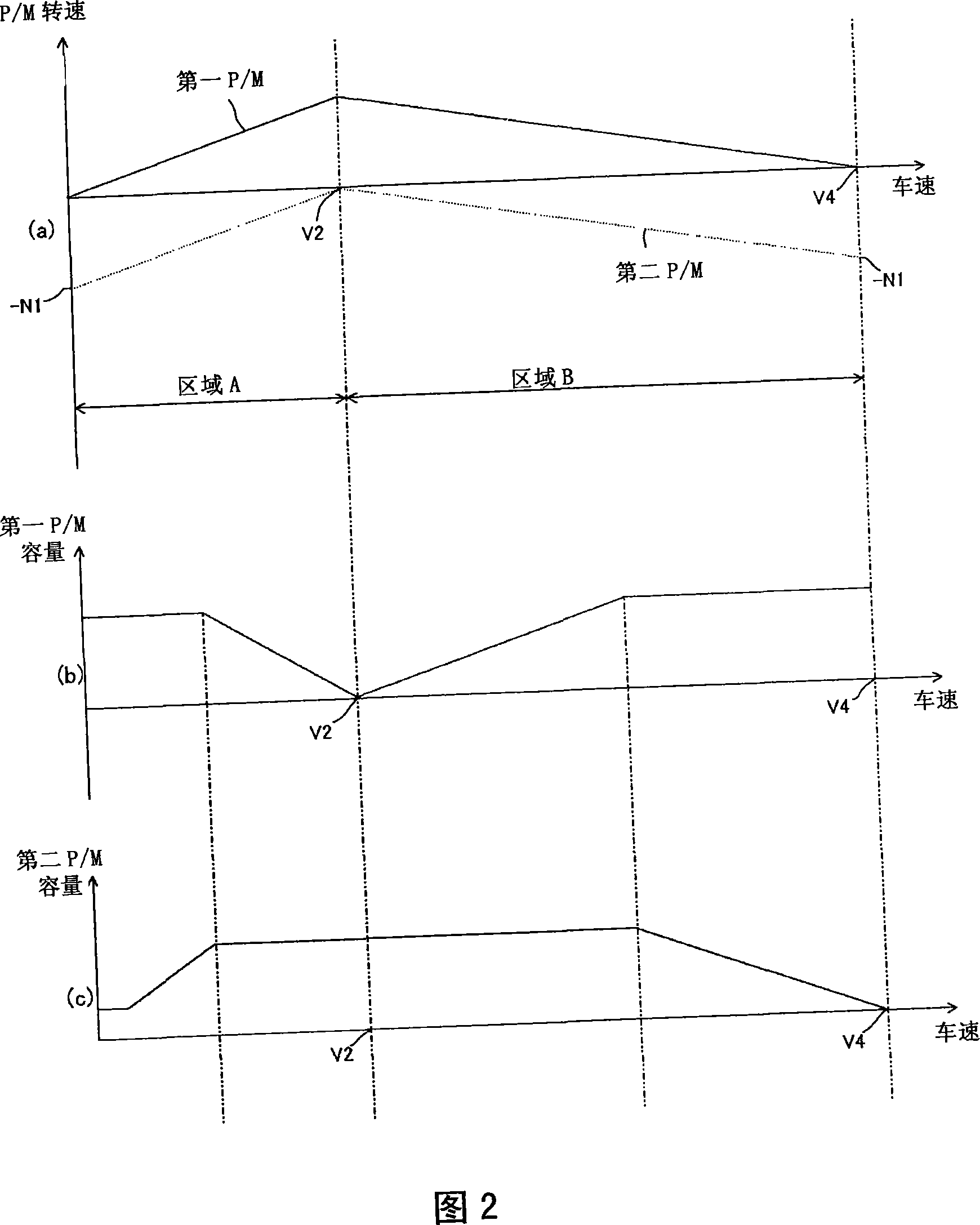
[0015] However, in the above-mentioned conventional transmission 100, when the second mode shown in FIG. The balance between (0~Nc) and the operating speed range (0~Nd) of the generator / motor 106 during the compound split mode becomes worse. As the generator / motor 106, it is necessary to select even at a relatively low speed Nd (<Nc) A large-capacity generator / motor that also exhibits sufficient capacity (torque), and as a result, there is a problem that a large and expensive generator / motor must be used
In addition, when the third mode shown in FIG. 17(c) is applied as the setting of the mode switching point, the operating speed range (0-Ne) of the generator / motor 106 in the input split mode and the speed range (0-Ne) in the combined split mode are input. The balance of the operating speed range (0 to Nf) of the generator / motor 106 deteriorates. As the generator / motor 106, it is necessary to select a capacity that can exert sufficient capacity (torque) even at a relatively low speed Ne (<Nf). Large generator / motor, still has the problem of having to use a large, expensive generator / motor
[0016] In addition, in the hydraulic-mechanical transmission (HMT) configured by using a pump / motor instead of the generators / motors 106 and 107 of the conventional transmission 100, a part of the mechanical power is converted into hydraulic power and transmitted. , which of course produces the same problem as stated

Method used


Image

  • Transmission apparatus
  • Transmission apparatus
  • Transmission apparatus

Examples


no. 1 approach

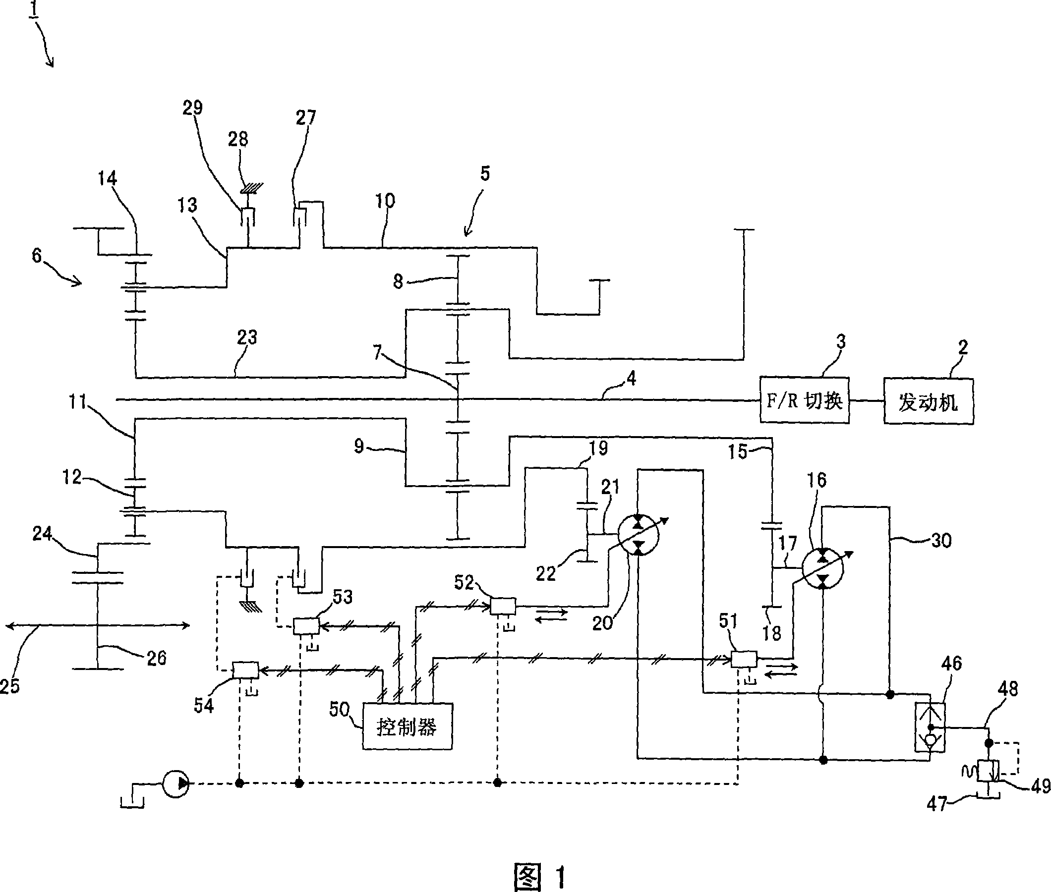
[0104] FIG. 1 shows a schematic configuration diagram of a transmission device according to a first embodiment of the present invention. This embodiment relates to examples applied to construction vehicles such as bulldozers and wheel loaders.

[0105] The transmission 1 of the present embodiment includes an input shaft 4 through which power from an engine 2 is input through a forward / reverse switching mechanism 3 , and a first planetary gear mechanism 5 and a second planetary gear mechanism 6 arranged coaxially with the input shaft 4 . .

[0106] The first planetary gear mechanism 5 has a sun gear 7 fixed to the input shaft 4, a plurality of planetary gears 8 meshing with the outer periphery of the sun gear 7, a planetary gear carrier 9 that pivotally supports the planetary gears 8, and The outer circumference of the set of planetary gears 8 meshes with a ring gear 10 . On the other hand, the second planetary gear mechanism 6 has a sun gear 11, a plurality of planetary gear...

no. 2 approach

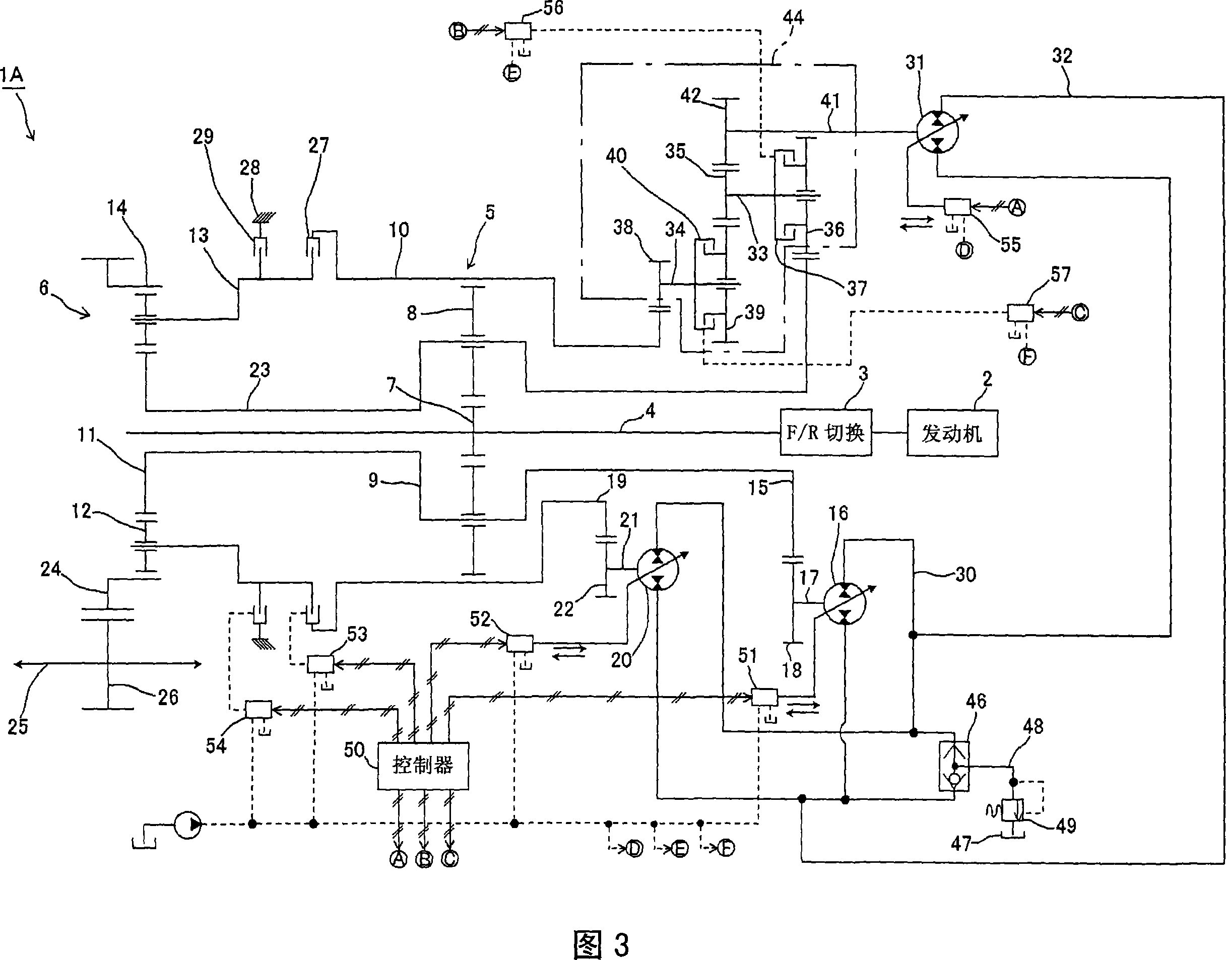
[0122] Fig. 3 is a schematic configuration diagram of a transmission device according to a second embodiment of the present invention. In addition, in this embodiment, the same part as the said 1st Embodiment is attached|subjected to the same code|symbol in a figure, and detailed description is abbreviate|omitted.

[0123] In the transmission device 1A of the present embodiment, the third pump / motor 31 is connected to the hydraulic piping 30 via the hydraulic piping 32 . The third pump / motor capacity adjusting device 55 that adjusts the capacity of the third pump / motor 31 in accordance with a command signal from the controller 50 is provided on the third pump / motor 31 . In addition, the first shaft 33 and the second shaft 34 are arranged parallel to the input shaft 4 , respectively.

[0124] A seventh gear 35 is fixed on said first shaft 33 , and an eighth gear 36 is engaged by a third clutch 37 . Furthermore, a ninth gear 38 is fixed on the second shaft 34 , and a tenth gea...

no. 3 approach

[0144] Fig. 6 is a schematic configuration diagram of a transmission device according to a third embodiment of the present invention. In addition, FIG. 7 shows an operation characteristic diagram of the transmission device according to the third embodiment. This embodiment is an example in which a switching valve 43 for switching the flow of pressurized oil to the third pump / motor 31 to always be in a certain direction is added to the transmission device 1A of the second embodiment. Therefore, in this embodiment, the same parts as those in the second embodiment are assigned the same reference numerals, and detailed descriptions thereof are omitted.

[0145] The transmission device 1B of the present embodiment is characterized in that a pump / motor of a pulsation specification is used as the third pump / motor 31 (see FIG. 7( d )). When the third pump / motor 31 is connected to the first pump / motor 16 side and when connected to the second pump / motor 20 side, the rotation direction ...


PUM


Abstract

A hydraulic-mechanical transmission apparatus or an electric-mechanical transmission apparatus where a pump / motor or a generator / motor having a smaller capacity than conventional ones can be used regardless of setting of a mode switching point that is the standard point of switching between an input split mode and a compound split mode. A transmission apparatus where a sun gear (7) of a first planetary gear mechanism (5) is connected to an input shaft (4), a carrier (9) of the first planetary gear mechanism (5) is connected to both a sun gear (11) of a second planetary gear mechanism (6) and a first pump / motor (16), a ring gear (10) of the first planetary gear mechanism (5) is connected to a second pump / motor (20), a ring gear (14) of the second planetary gear mechanism (6) is connected to an output shaft (25), a first clutch (27) for connecting or disconnecting a carrier (13) of the second planetary gear mechanism (6) and the ring gear (10) of the first planetary gear mechanism (5) is provided in the transmission apparatus, and a second clutch for connecting or disconnecting the carrier (13) of the second planetary mechanism (6) and a stationary end (28) is provided in the transmission apparatus.

Description

technical field [0001] The present invention relates to a hydraulic-mechanical or electro-mechanical speed change device composed of a combination of a pump / motor or a generator / motor and a planetary gear mechanism. Background technique [0002] Conventionally, as a hydraulic transmission, a purely hydraulic transmission (Hydraulic Static Transmission: HST) that converts all the input power from the engine into hydraulic pressure and transmits it, hydraulically transmits a part of the input power and mechanically transmits it is known. The rest is a hydraulic-mechanical (power split) transmission (hydromechanical transmission: HMT). Among them, the latter transmission device (HMT) only needs to convert part of the mechanical power into hydraulic power, and the transmission efficiency of mechanical power is high. Compared with the former transmission device (HST), it has the advantage of achieving high efficiency. For bulldozers It is an ideal transmission for vehicles with ...

Claims


Application Information

Patent Timeline
IPC IPC(8): F16H47/04B60K17/04B60L11/14F16H3/66F16H3/72F16H61/32B60K6/365B60L50/16
CPCF16H61/4043Y02T10/6239F16H2047/045F16H2037/106F16H2037/108F16H47/04F16H2200/2041B60W10/08F16H2037/0866B60W20/00F16H2037/0873B60W10/02F16H2200/2035B60K6/445F16H2037/104B60K17/10F16H3/728F16H2200/2007B60L1/003B60L15/20B60L15/2054B60L2200/40B60L2240/12B60L2240/421B60L2240/441B60L2240/461B60L2240/486B60L2240/507Y02T10/72B60L50/61B60L50/16Y02T10/62Y02T10/64Y02T10/7072Y02T10/70B60K17/04F16H3/72
Inventor 平木彦三郎小松健浩
Owner KOMATSU LTD
Learn More