
Prestressed bracing arrangement

A support device and prestressing technology, which is applied in the direction of house structure support, house structure support, scaffolding accessories, etc., can solve the problems of calculating additional force, poor controllability of accuracy, difficulty, etc., and achieve a simple and stable structure of the support device. The effect of good performance and easy construction and operation

Inactive Publication Date: 2008-05-28
CENT RES INST OF BUILDING & CONSTR CO LTD MCC GRP +1
View PDF0 Cites 3 Cited by
  • Summary
  • Abstract
  • Description
  • Claims
  • Application Information

AI Technical Summary

Problems solved by technology

[0003] Among them, the scaffolding support is a passive support device, that is, it only plays a supporting role when the load is applied to the device after the structure is deformed by force. This kind of support is mainly used in the wet operation process of civil structures, or for problems Protective support for structural components to prevent further expansion of the problem, etc., but the scaffold support cannot exert accurate support force on the structure;
[0004] The combined support of jack and steel column is an active support device, that is, the support force is applied to the structure through the jack. And the controllability in the process of application is poor, that is, the error of the supporting force provided is large, and the construction process is not easy to operate; and the combined support of the jack and steel column is stable after the supporting force is applied to the structure. It is difficult to control, if the structure deforms at the support point, the support force will be weakened obviously
After this happens, if you want to add support force at the original support point, how to accurately calculate the size of the additional force and how to implement this force are very difficult

Method used


Image

  • Prestressed bracing arrangement
  • Prestressed bracing arrangement
  • Prestressed bracing arrangement

Examples


Embodiment Construction

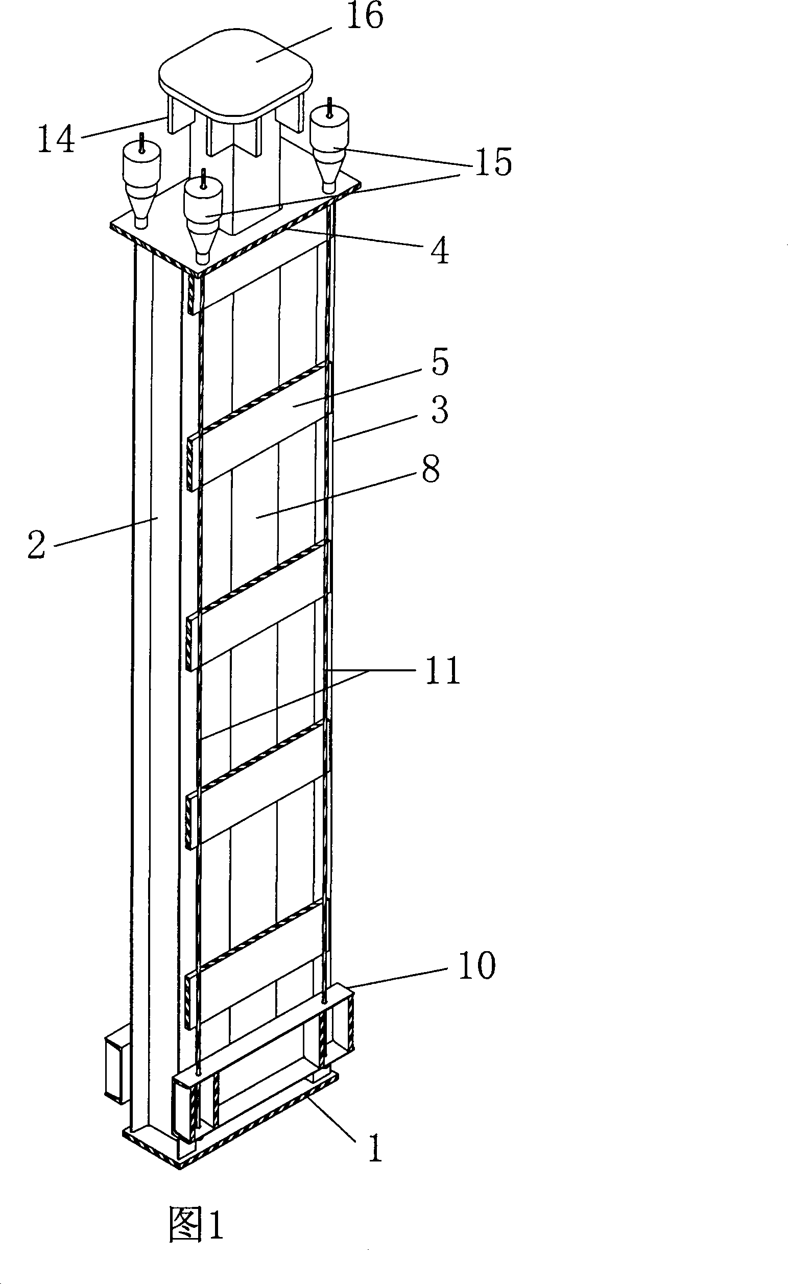
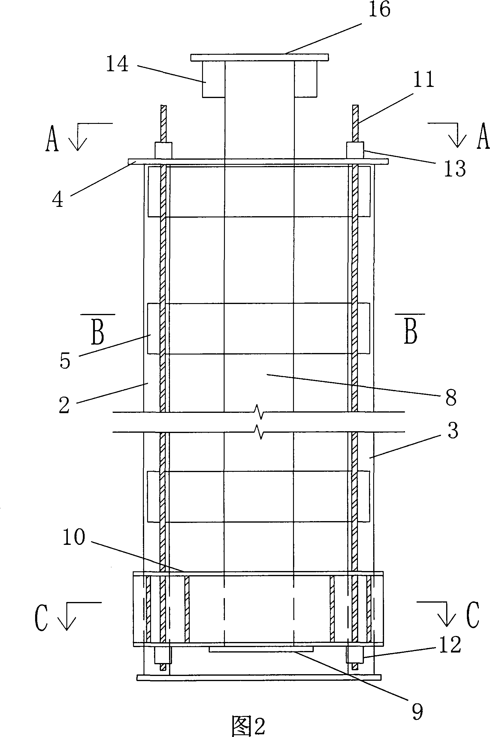
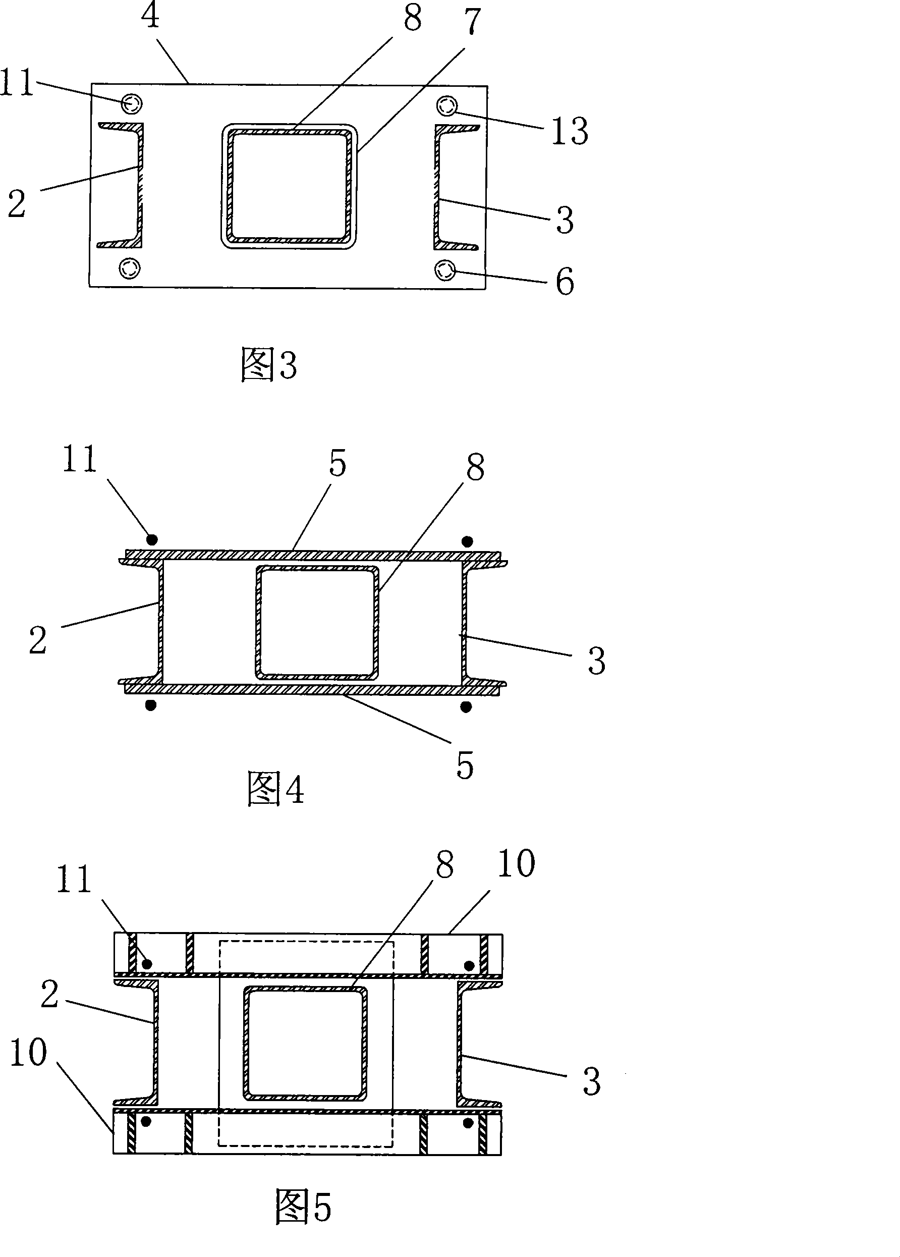
[0017] As shown in Figure 1, Figure 2, Figure 3, Figure 4, and Figure 5, a prestressed support device of the present invention is characterized in that it includes:

[0018] A support frame composed of a bottom plate 1, a left side plate 2, a right side plate 3 and a top plate 4. The two sides of the left side plate 2 and the right side plate 3 are vertically connected with the left side plate 2 and the right side plate The connecting plate 5 of 3, the top plate 4 is provided with a through hole 6 at the four corners, and the middle of the top plate 4 is provided with a large hole 7;

[0019] A steel column 8 located inside the support frame. The steel column 8 penetrates the large hole 7 of the top plate of the support frame. The two sides of the lower end of the steel column 8 are fixedly connected with two steel columns located on the outside of the support frame through the steel column bottom plate 9. Foot 10, each steel column foot 10 has a pre-stressed steel stranded wire 1...


PUM


Abstract

The invention relates to a prestressed support device, which comprises a braced frame which is constituted by a bottom plate, a left lateral plate, a right lateral plate, and a top plate. A plurality of connection boards which are used for connecting the left lateral board and the right lateral board are arranged on both sides of the left lateral board and the right lateral board along the vertical direction, through holes are arranged on the four corners of the top plate, a big hole is arranged on the center of the top plate, a steel column is arranged in the braced frame, which is sleeved in the big hole of the top plate of the braced frame, both sides on the lower end of the steel column are fixedly connected with two steel column feet which are arranged on the outer side of the braced frame, a prestressed steel strand wire is respectively sleeved through two ends of each steel column foot, the lower end of each prestressed steel strand wire is fixedly connected with a crimping anchorage for supporting steel column feet, the upper ends of the four prestressed steel strand wires are respectively traversed through the four through holes of the top plate of the braced frame and are fixedly connected with clipping anchorages. The invention can provide anchorage force with high accuracy and excellent stability for supported constructions, and provides a prestressed support device which is easy for construction.

Description

Technical field [0001] The invention relates to a supporting device in construction engineering, in particular to a pre-stressed supporting device. Background technique [0002] Supporting devices are often used in the construction process of construction projects. At present, the more commonly used supporting devices include erected scaffolding supports and combined supports of jacks and steel columns. [0003] Among them, the scaffold support is a passive support device, that is, because the load is applied to the device after the structure is deformed, it plays a supporting role. This kind of support is mainly used in the wet work process of the civil structure, or for the problem Protective support for structural members to prevent further expansion of the problem, etc., but the scaffolding support cannot provide accurate support for the structure; [0004] The combined support of the jack and the steel column is an active support device, that is, the support force is applied...

Claims


Application Information

Patent Timeline
IPC IPC(8): E04G5/04E04G21/12
Inventor 吴明超尚仁杰刘刚宫锡胜
Owner CENT RES INST OF BUILDING & CONSTR CO LTD MCC GRP
Learn More