Electric actuator

A technology of electric actuators and electric motors, applied in the direction of electric components, electrical components, electromechanical devices, etc., can solve the problems that electric actuators cannot be realized, and achieve the effect of high controllability and high output

Inactive Publication Date: 2008-05-28
THK CO LTD
View PDF0 Cites 18 Cited by
  • Summary
  • Abstract
  • Description
  • Claims
  • Application Information

AI Technical Summary

Problems solved by technology

However, in the conventional technology, it is impossible to realize an electric actuator that can be housed in the same installation space as the hydraulic cylinder body and can achieve the same high output as the hydraulic cylinder.

Method used


Image

  • Electric actuator
  • Electric actuator
  • Electric actuator

Examples


no. 1 Embodiment approach

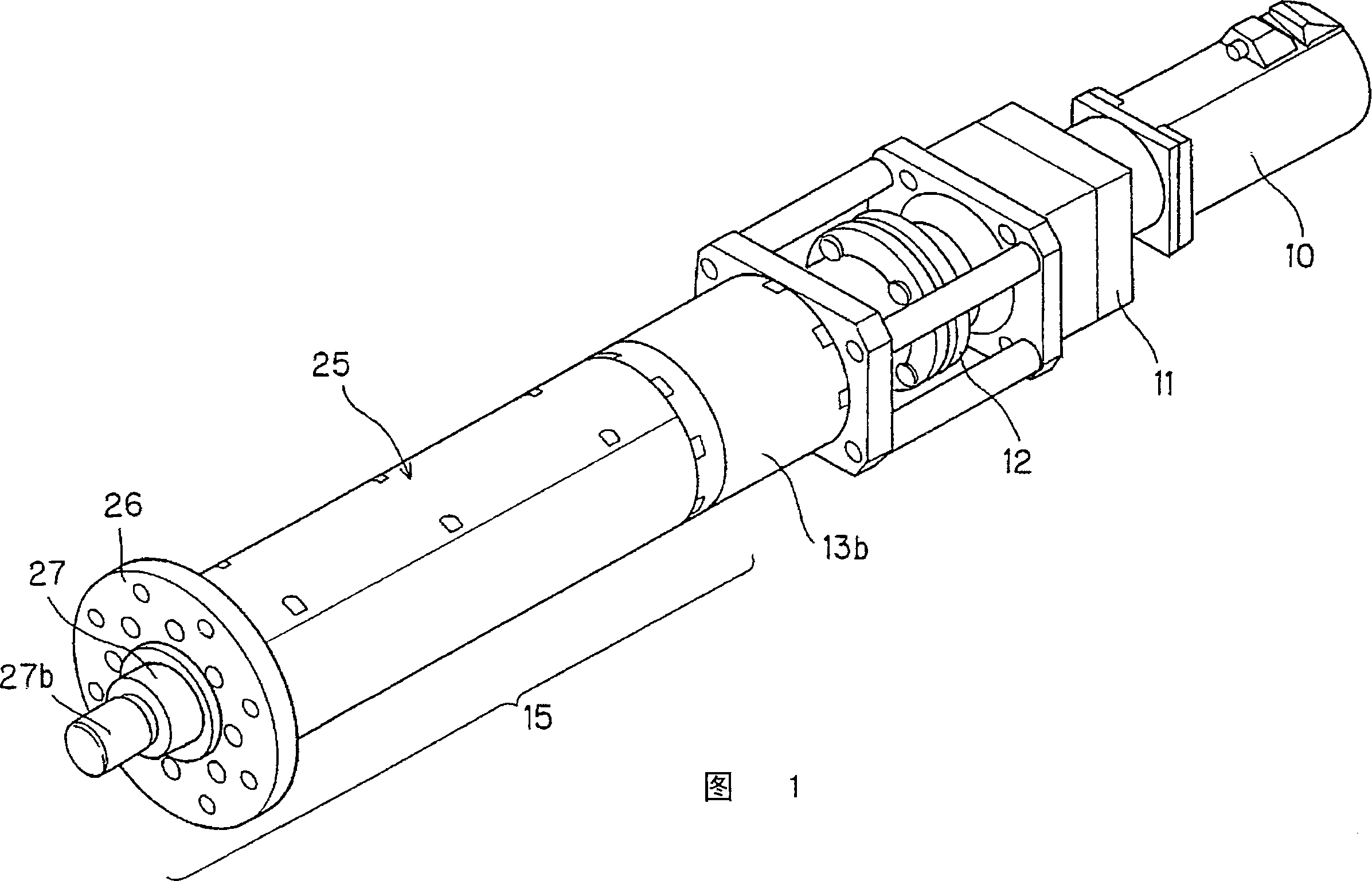
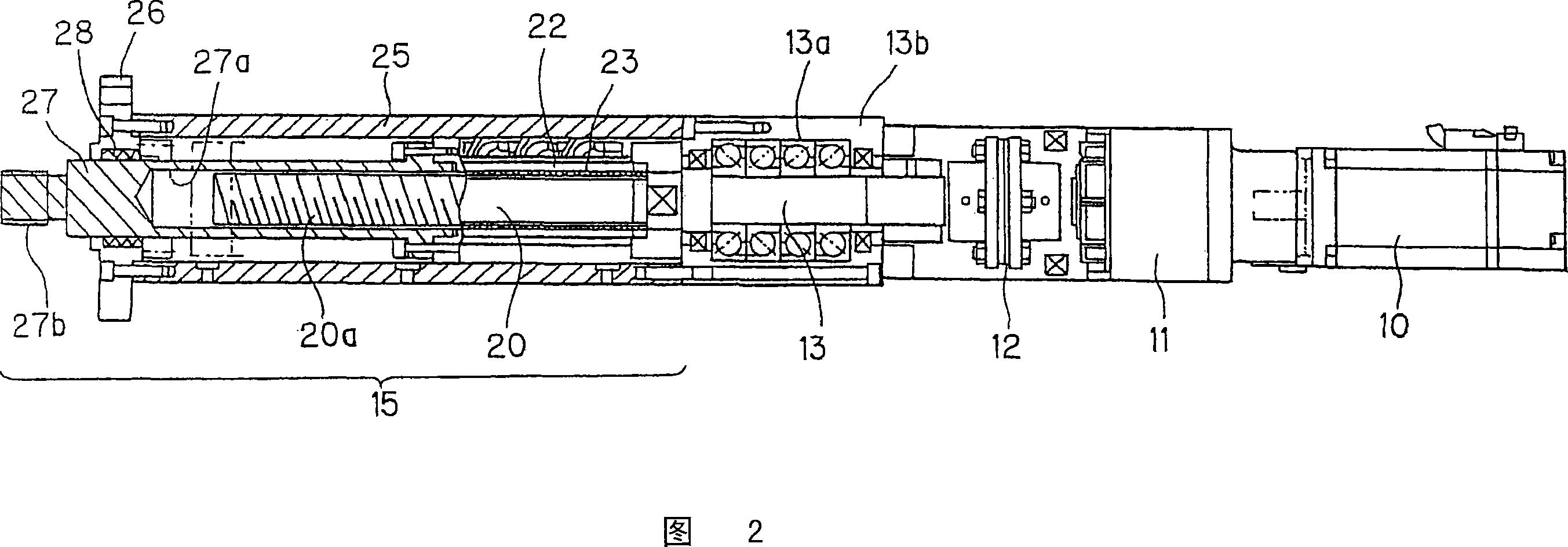
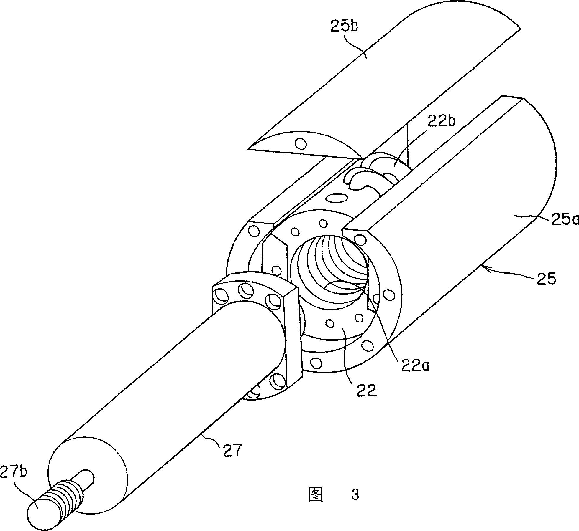
[0034] FIG. 1 is an external perspective view showing the overall configuration of an electric actuator according to a first embodiment. In addition, FIG. 2 is a longitudinal sectional side view of the electric actuator according to the first embodiment.

[0035] The electric actuator of the first embodiment includes an electric motor 10 as a drive source. The electric motor 10 is provided at an end portion opposite to the installation position of the cylinder rod 27 as an action portion, and a rotational driving force is provided by an output shaft of the electric motor 10 .

[0036] On the output shaft of the electric motor 10, a speed reducer 11 for increasing torque amplification, increasing inertial force, reducing vibration, etc. is provided continuously. In addition, a connecting shaft 13 supported by a coupling 12 and a rolling bearing 13 a is provided at an end of the speed reducer 11 , and a power transmission mechanism 15 is further provided at an end thereof. In ...

no. 2 Embodiment approach

[0069] In the above-mentioned first embodiment, the case where the components of the electric actuator such as the electric motor 10 , the speed reducer 11 , the coupling 12 , the connecting shaft 13 , and the power transmission mechanism 15 are connected in series has been described as an example. In the second embodiment described below, an electric actuator suitable for use when the installation space in the axial direction is limited will be described. In addition, the same code|symbol is attached|subjected to the component demonstrated in 1st Embodiment, or a similar component, and description is abbreviate|omitted.

[0070] 9 is an external perspective view showing the overall configuration of an electric actuator according to a second embodiment. In addition, FIG. 10 is a longitudinal sectional plan view of the electric actuator of the second embodiment.

[0071] In the electric actuator of the second embodiment, the coupling provided in the first embodiment is omitted...


PUM


Abstract

An electric actuator has a power transmission mechanism (15) capable of converting a rotational drive force, supplied from an electric motor (10), into reciprocating motion. The power transmission mechanism (15) is composed of a tubular member (25) having in its inner peripheral surface at least a line of rolling body rolling groove, a nut member (22) reciprocatably placed on the inner peripheral surface of the tubular member (25) with endlessly circulating rolling bodies in between, a cylinder rod (27) connected to an end of the nut member (22) and placed so as to be advanceable and retreatable relative to the tubular member (25). The nut member (22) is guided for axial reciprocating motion by the tubular member (25) having a substantially circular tube shape. The electric actuator has high output and high controllability and is compact, about the size of a conventional oil-hydraulic cylinder.

Description

technical field [0001] The present invention relates to an electric actuator, and relates to a new electric actuator that is driven by an electric motor as a drive source and can be used instead of a conventionally used hydraulic cylinder. Background technique [0002] Hydraulic cylinders are generally used as actuators for realizing telescopic motion of mechanical devices such as an injection device of an injection molding machine or a link mechanism of a construction machine. In this hydraulic cylinder, the pressure and the flow rate of the hydraulic oil are changed by changing the capacity of the variable pump that is the source of the pressure oil supply, thereby maximizing the output and realizing a wide speed range and thrust range at the same time. [0003] The hydraulic cylinder driven in this way includes a hydraulic cylinder main body that expands and contracts, and a hydraulic pressure generating device that supplies pressurized oil to the hydraulic cylinder main ...

Claims


Application Information

Patent Timeline
Patent Type & Authority Applications(China)
IPC IPC(8): F16H25/24H02K7/06
CPCH02K7/06F16H25/2204F16H2025/204F16H2025/2075Y10T74/18032F16H25/24
Inventor 寺町彰博道冈英一浅生利之堀池一也
Owner THK CO LTD
Why Eureka
Try Eureka