Boat hull surface buffering shock-absorbing device
A technology of vibration damping device and hull, which is applied in the direction of hull, hull parts, hull, etc., can solve the problems of not finding a buffer and vibration damping method and device, changing the dynamic performance of the ship, and rapidly eroding, so as to achieve better vibration damping effect. The effect of good vibration isolation effect and broad application prospect
- Summary
- Abstract
- Description
- Claims
- Application Information
AI Technical Summary
Problems solved by technology
Method used
Image
Examples
Embodiment 1
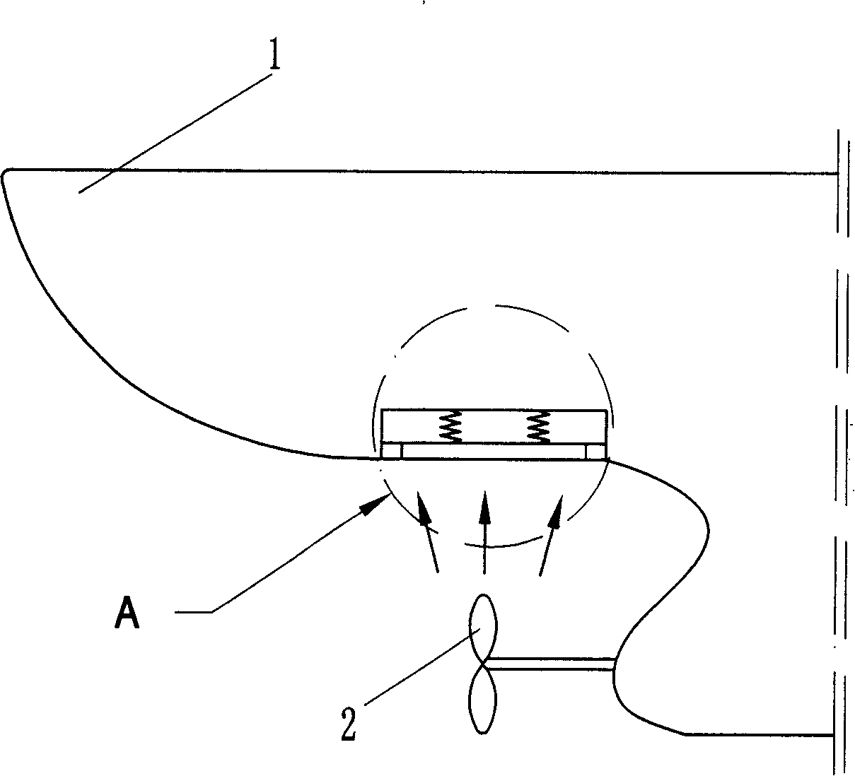
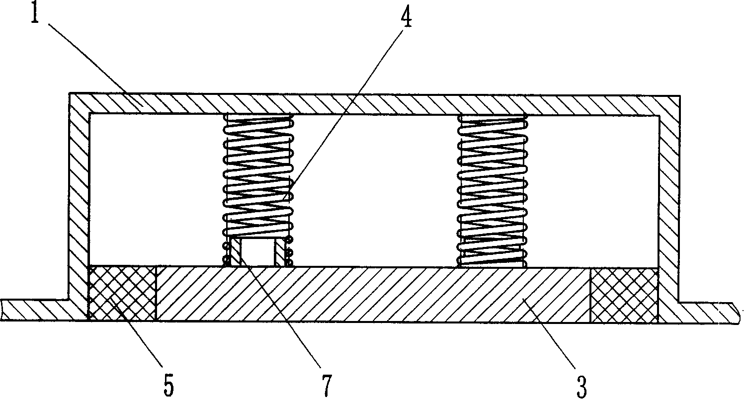
[0022] Such as figure 1 , figure 2 As shown, the hull surface buffering and damping device of the present invention is arranged on the hull 1 above the propeller 2, and the hull surface buffering and damping device includes a baffle plate 3, a steel spring 4 as an elastic element and an elastic spring 4 as a sealing element. rubber5. Wherein, the elastic rubber 5 is connected with the hull 1 and the baffle 3 as a whole through vulcanization. For positioning considerations, centering rings 7 are respectively provided on the hull 1 and the baffle 3 , and the two ends of the steel spring 4 are positioned by using the centering rings 7 . The steel spring 4 can also be fixed on the hull 1 or / and the baffle plate 3 if necessary.
[0023] When the ship is sailing, the propeller rotates and stirs the water flow to form a periodic exciting force on the upper impact, and the exciting force will excite the vibration of the hull. Because the surface of the hull above it is equipped wi...
Embodiment 2
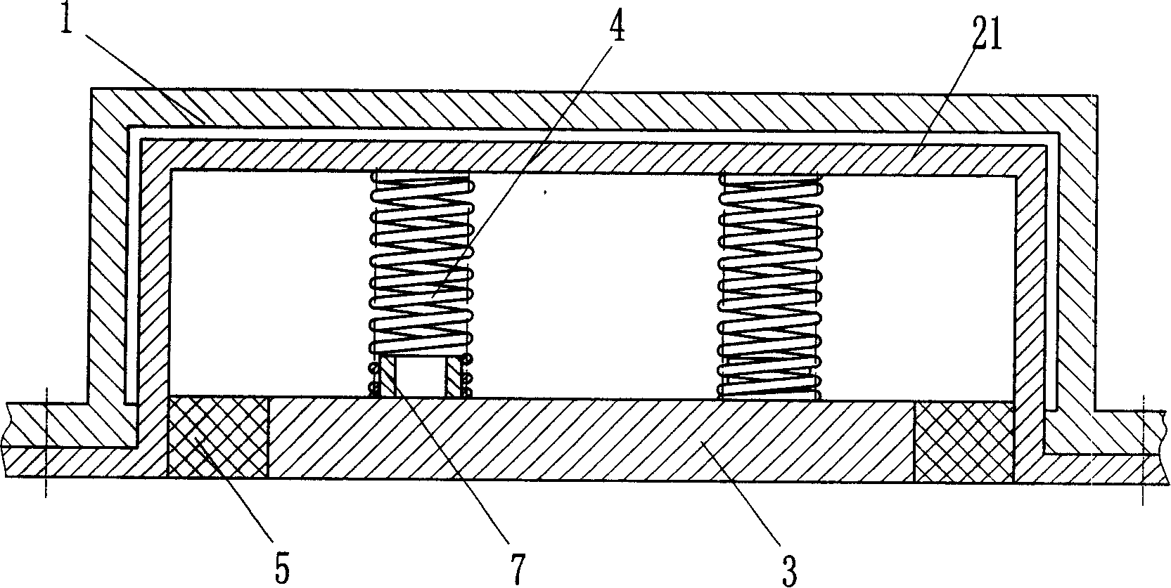
[0027] Such as image 3 As shown, the difference from Embodiment 1 is that a connecting box 21 is added, the steel spring 4 is located between the baffle plate 3 and the connecting box 21, and a centering ring for positioning elastic elements is set on the connecting box 21 accordingly. 7. The elastic rubber 5 as a sealing element is connected with the connection box 21 and the baffle 3 as a whole through vulcanization. After the above-mentioned structure is assembled, it is integrally fixedly connected to the hull 1 by fasteners to form the hull surface buffer and vibration damping device of the present invention. Of course, the connection with the hull here can also be welded connection or other fixed connection methods, all of which can achieve the same effect.
[0028] If the space between the baffle and the connecting box is filled with water, the baffle will squeeze and pull the water body when it vibrates. Since the water body is difficult to escape, the stiffness of ...
Embodiment 3
[0031] Such as Figure 4 As shown, the difference from Embodiment 1 is that the sealing element is elastic polyurethane 5. In order to prevent the water flow from directly impacting the elastic polyurethane 5 and cause the seal to be damaged too quickly, a protective plate for blocking the sealing area is welded on the side of the baffle plate 3 8. In order to facilitate the replacement of the steel spring 4, a detachable flange 6 is provided at the corresponding position of the hull 1 and the steel spring 4, and a gasket 22 is used for sealing in order to prevent leakage. In consideration of positioning and easy replacement, one end of the steel spring 4 is fixedly bonded to the flange 6 .
PUM
 Abstract
Description
Claims
Application Information
 - R&D
- Intellectual Property
- Life Sciences
- Materials
- Tech Scout
- Unparalleled Data Quality
- Higher Quality Content
- 60% Fewer Hallucinations
Browse by: Latest US Patents, China's latest patents, Technical Efficacy Thesaurus, Application Domain, Technology Topic, Popular Technical Reports.
© 2025 PatSnap. All rights reserved.Legal|Privacy policy|Modern Slavery Act Transparency Statement|Sitemap|About US| Contact US: help@patsnap.com


