
Light source unit and backlight module group possessing same

The technology of a backlight module and a light source unit is applied in the directions of optics, electrical components, nonlinear optics, etc., and can solve problems such as inconvenience, the inability to shorten the light mixing distance d1, and the difficulty of thinning the backlight module 10, so as to shorten the distance, The effect of shortening the mixing distance

Inactive Publication Date: 2008-06-04
LITE ON TECH CORP
View PDF0 Cites 10 Cited by
  • Summary
  • Abstract
  • Description
  • Claims
  • Application Information

AI Technical Summary

Problems solved by technology

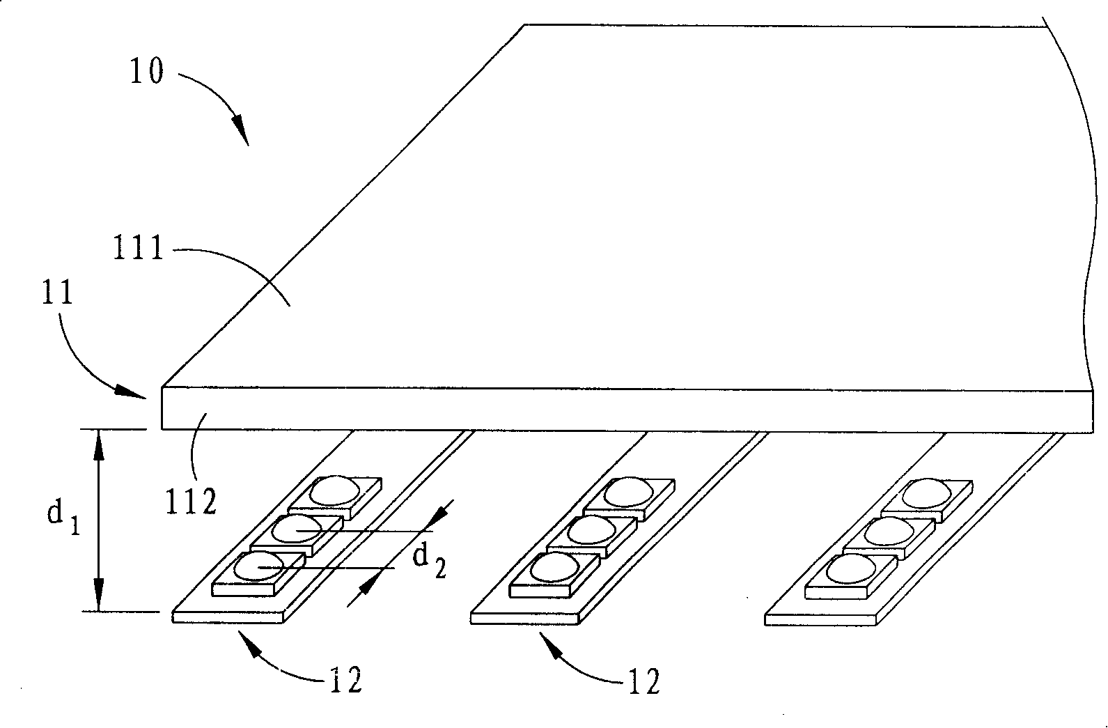
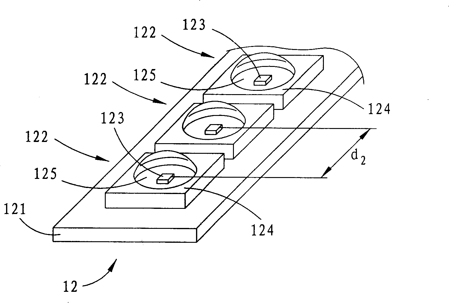
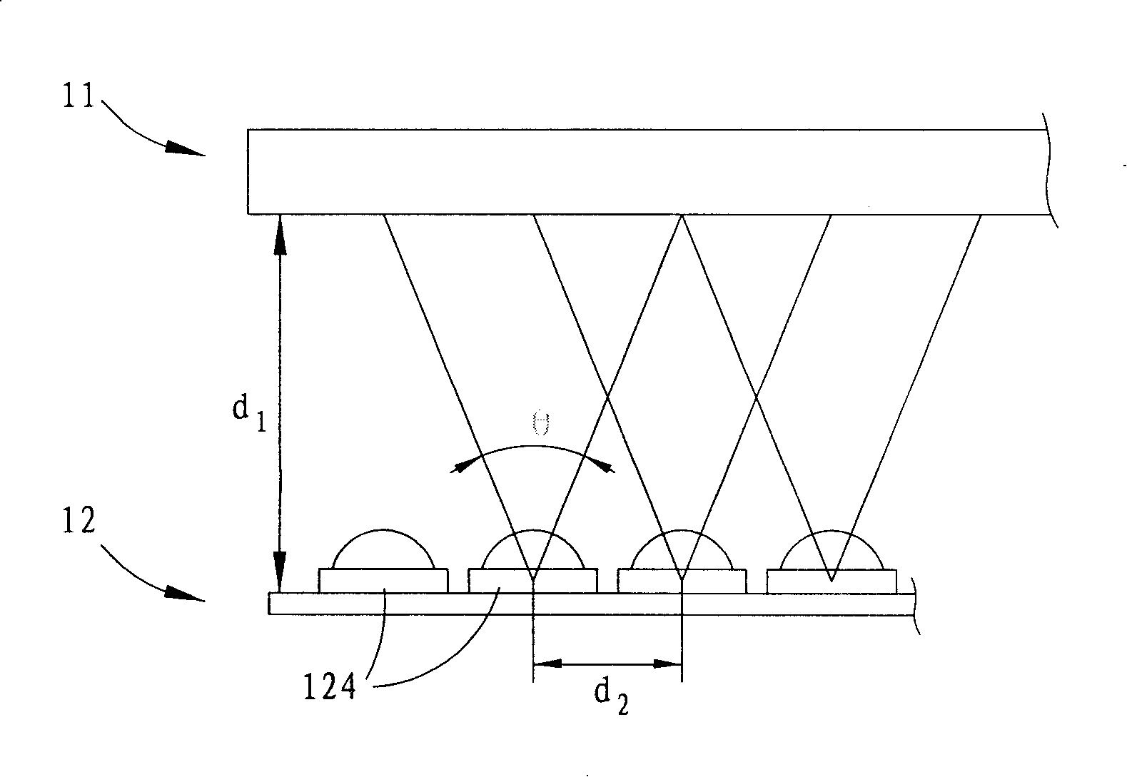
[0010] However, as mentioned above, the general light source unit 12 is a packaged light-emitting diode. If the grain distance d2 is to be further reduced, it will be limited by the volume of the package base 124 and it is not easy to achieve, resulting in the light mixing distance d1 It cannot be shortened, and the distance between the light incident surface of the light guide plate 11 and the light source unit 12 is also difficult to shorten, so that the backlight module 10 is not easy to be further thinned.
[0011] It can be seen that the above-mentioned existing light source unit and backlight module obviously still have inconvenience and defects in structure and use, and need to be further improved urgently.
In order to solve the above-mentioned problems, the relevant manufacturers have tried their best to find a solution, but no suitable design has been developed for a long time, and the general products do not have a suitable structure to solve the above-mentioned problems. This is obviously related. The problem that the industry is eager to solve

Method used


Image

  • Light source unit and backlight module group possessing same
  • Light source unit and backlight module group possessing same
  • Light source unit and backlight module group possessing same

Examples


Embodiment Construction

[0087] In order to further explain the technical means and effects of the present invention to achieve the intended purpose of the invention, the light source unit proposed according to the present invention and the backlight module with the light source unit are specifically implemented below in conjunction with the accompanying drawings and preferred embodiments. The method, structure, characteristics and effects thereof are described in detail as Kai.

[0088] The aforementioned and other technical contents, features and effects of the present invention will be clearly presented in the following detailed description of a preferred embodiment with reference to the drawings.

[0089]Before the present invention is described in detail, it should be noted that in the following description, similar elements are denoted by the same numerals.

[0090] see Figure 4 As shown, it is a preferred embodiment of the light source unit 2 used in the backlight module of the present invent...


PUM


Abstract

The invention provides a light source unit and a backlight module provided with the light source unit. The light source unit for the backlight module provided by the invention comprises a circuit board and a plurality of crystal grain combinations which are arranged along a first direction of the circuit board. Each crystal grain combinations comprises a red light LED crystal grain, a blue light LED crystal grain and a green light LED crystal grain. By adopting the conception of COB, the tricolor LED crystal grains are directly arranged on the circuit board, which ensures that the space between crystal grains is greatly decreased, effectively shortens the light mixing distance, and ensures that the backlight module of the light source unit is thinner and lighter.

Description

technical field [0001] The present invention relates to a light source unit and a backlight module with the light source unit, in particular to a light source unit capable of shortening the light mixing distance to achieve thinning and a backlight module with the light source unit. Background technique [0002] Under the trend of thinning liquid crystal display modules, the backlight module used to provide the planar light source of the liquid crystal display module must also be continuously improved in structure to achieve the goal of thinning. [0003] At the same time, under the continuous pursuit of better color performance of liquid crystal display modules and environmental protection considerations, cold cathode fluorescent lamps (CCFL) used in general backlight modules will gradually be replaced by light-emitting diodes with better color rendering and no mercury. (LED) replaced. [0004] see figure 1 As shown, a direct-lit backlight module 10 generally using light-e...

Claims


Application Information

Patent Timeline
IPC IPC(8): G02F1/13357G02F1/133H01L33/00G09G3/34G02F1/1335
Inventor 潘昶宏黄祯华
Owner LITE ON TECH CORP
Learn More