Boiler furnace of circulating fluidized bed with water-cooled column
A circulating fluidized bed and boiler furnace technology, which is applied to fluidized bed combustion equipment, fuel burning in a molten state, lighting and heating equipment, etc., can solve the effect of furnace material circulation, furnace material concentration, temperature distribution and heat transfer uniformity. It can improve hydrodynamic safety, uniform heating, and reduce NOx emissions.
- Summary
- Abstract
- Description
- Claims
- Application Information
AI Technical Summary
Problems solved by technology
Method used
Image

Examples
Embodiment 1
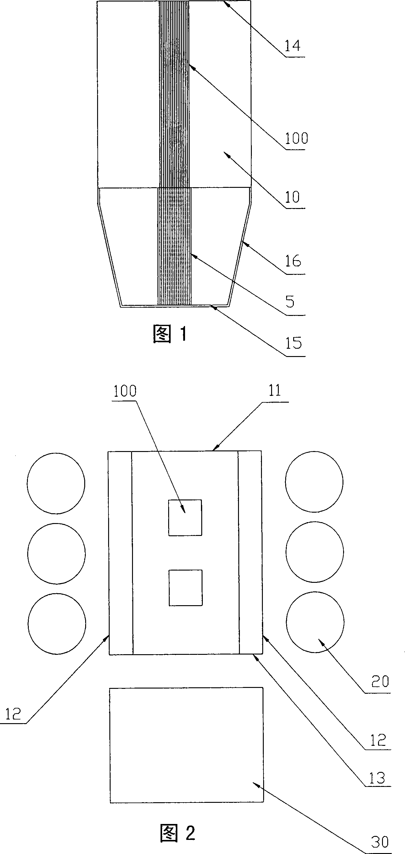
[0021] Referring to Fig. 1, Fig. 2 and Fig. 3, the furnace 10 of the circulating fluidized bed boiler with water-cooled columns of the present invention comprises a furnace front wall 11, a rear wall 13, two side walls 12, a ceiling 14 and an air distribution plate 15, and the two side walls Cyclone separators 20 are arranged symmetrically on the outside, and the rear side of the rear wall is a tail flue 30 .
[0022] Between the furnace air distribution plate 15 and the ceiling 14, two vertical water-cooling columns 100 are arranged along the center line of the depth of the furnace 10 (perpendicular to the direction of the front and rear walls of the furnace), and the water-cooling columns 100 are surrounded by membrane walls 1 of square columns without top and bottom faces. The position corresponding to the top of the water-cooling column 100 on the ceiling 14 and the position corresponding to the bottom of the water-cooling column 100 on the air distribution plate 15 are op...
Embodiment 2
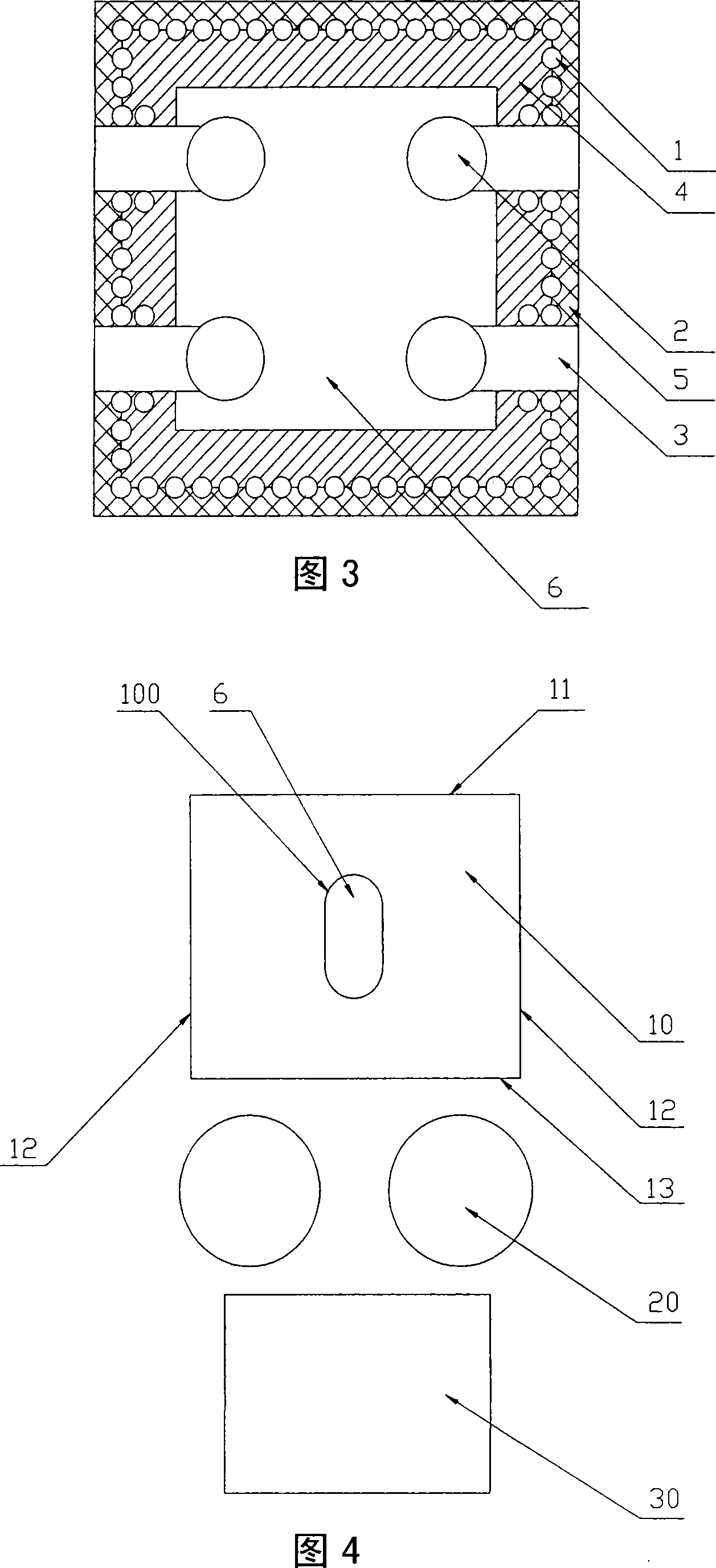
[0026] Referring to Fig. 1 and Fig. 4, the circulating fluidized bed boiler furnace 10 with water-cooled column of the present invention comprises furnace front wall 11, rear wall 13, side walls 12, ceiling 14 and air distribution plate 15, rear wall 13 and tail smoke Cyclone separators 20 are arranged between the channels 30 .
[0027] A vertical water-cooling column 100 is arranged between the furnace air distribution plate 15 and the ceiling 14. The water-cooling column 100 is surrounded by a membrane wall, and the cross-sectional shape is oblong, and the two semicircles face the front wall and the rear of the furnace respectively. wall. The water-cooled column-membrane wall tube has a working fluid from bottom to top. The outer side of the water cooling column faces the combustion space of the furnace. In order to ensure the same heating condition between the water cooling column and the water cooling wall of the furnace, refractory materials with the same height as the ...
PUM
 Abstract
Description
Claims
Application Information
 - R&D
- Intellectual Property
- Life Sciences
- Materials
- Tech Scout
- Unparalleled Data Quality
- Higher Quality Content
- 60% Fewer Hallucinations
Browse by: Latest US Patents, China's latest patents, Technical Efficacy Thesaurus, Application Domain, Technology Topic, Popular Technical Reports.
© 2025 PatSnap. All rights reserved.Legal|Privacy policy|Modern Slavery Act Transparency Statement|Sitemap|About US| Contact US: help@patsnap.com