Non-contact type strain measurement method based on visual discrimination

A non-contact, strain measurement technology, applied in measuring devices, image data processing, instruments, etc., can solve the problems of inability to measure the tensile properties of micro-devices and easily damaged test pieces

Inactive Publication Date: 2008-06-11
HARBIN INST OF TECH
View PDF0 Cites 25 Cited by
  • Summary
  • Abstract
  • Description
  • Claims
  • Application Information

AI Technical Summary

Problems solved by technology

[0004] The purpose of the present invention is to provide a non-contact strain measurement method based on visual discrimination, so as to overc...

Method used


Image

  • Non-contact type strain measurement method based on visual discrimination
  • Non-contact type strain measurement method based on visual discrimination
  • Non-contact type strain measurement method based on visual discrimination

Examples


specific Embodiment approach 1

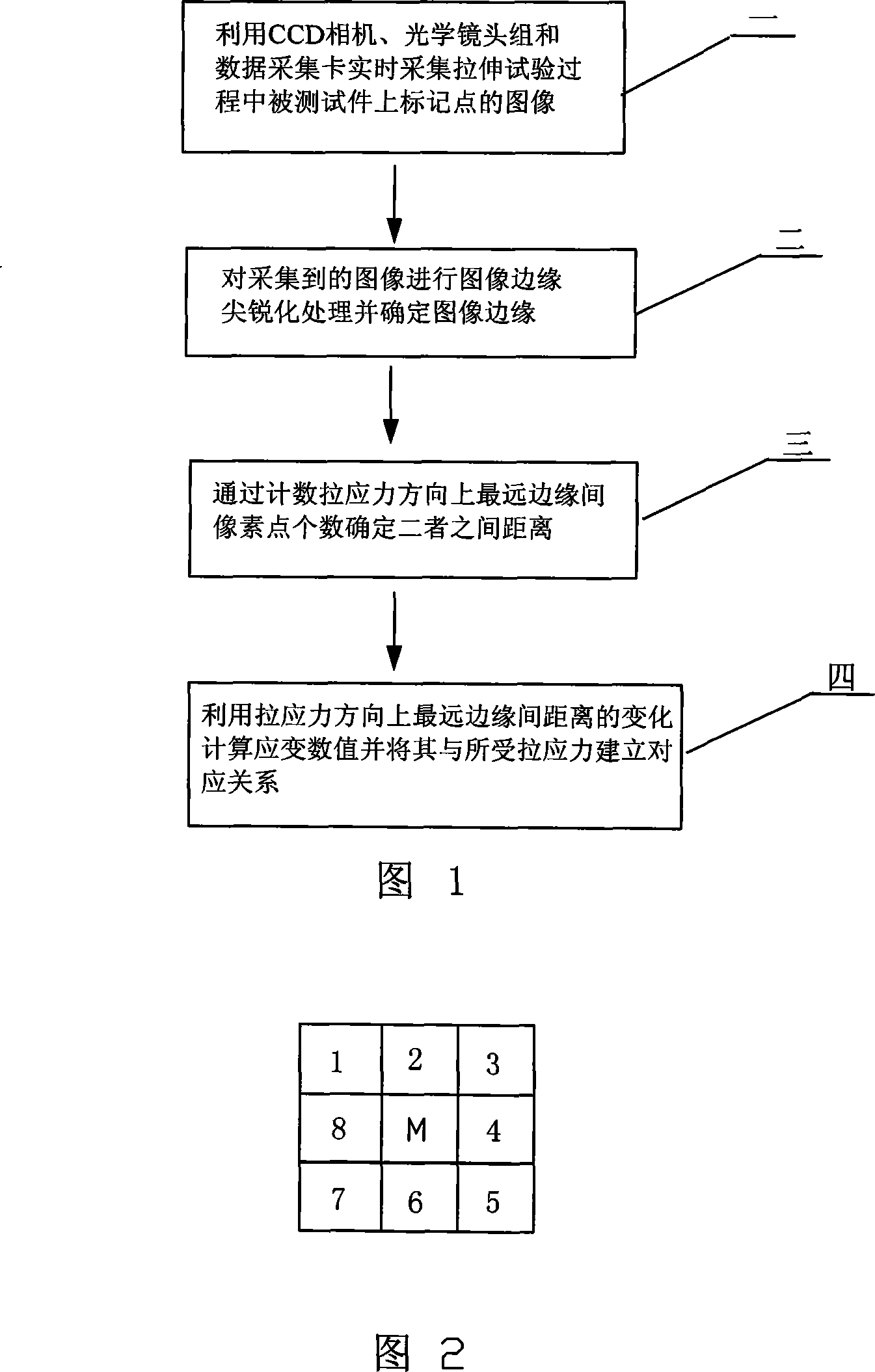
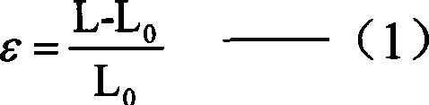
[0007] Specific Embodiment 1: The present embodiment will be specifically described below with reference to FIG. 1 . This embodiment consists of the following steps: 1. Using a CCD camera, an optical lens group and a data acquisition card to collect in real time the images of the marked points on the test piece during the tensile test; 2. Sharpening the edges of the collected images Process and determine the edge of the image; 3. Determine the distance between the two by counting the number of pixels between the farthest edges in the direction of tensile stress; 4. Calculate the strain value using the change in the distance between the farthest edges in the direction of tensile stress and compare it with The corresponding relationship is established for the tensile stress.

[0008] The CCD camera adopts MTV-1881EX black and white industrial camera, and the data acquisition card is a PCI image acquisition card of the OK-M10A model. The optical lens group is placed in front of ...

specific Embodiment approach 2

[0010] Specific embodiment two: the difference between this embodiment and embodiment one is: step two of embodiment one is made up of the following steps: A, use Gaussian filter to carry out smooth processing to the image that comes in, to suppress the interference of noise; B. Calculate the gradient magnitude and direction of each pixel of the smoothed image, and highlight the points with significant gradient magnitude changes, thereby enhancing the edge display of the image. The specific process is as follows: use the formula (2) to calculate the gradient magnitude and direction of each pixel of the smoothed image,

[0011]

[0012]

[0013] Formulas (2) and (3) are used to calculate the gradient magnitude and direction,  x (m, n) is the gradient in the x direction,  y (m, n) Gradient in the y direction, (m, n) is the gradient magnitude, θ(m, n) is the gradient direction, and the points with significant changes in the gradient magnitude are highlighted, that is, t...


PUM


Abstract

A non-contact strain measuring method based on visual discrimination is provided, which relates to the strain measuring method of miniature device. The invention overcomes the defect that using the traditional contact extensometer or strain foil is unable to measure the tensile property of miniature device and is easy to damage the test piece. Firstly, use CCD camera, optical lens set and data collecting card to collect the image of the mark on the tested piece during tension test process; secondly, conduct quickness processing to the edge of the collected image; thirdly, fix the distance between two points according to the quantity of pixels in the furthest edge in the direction of tension force; fourthly, utilize the change of the distance in the furthest edge in the direction of tension force to count the strain value and build corresponding relationship with the received tension. The invention can precisely measure the strain in the single-direction tension test of miniature device or micro-forming material, which has the advantages of no abrasion, strong anti-interference performance and high precision.

Description

technical field [0001] The invention relates to a strain measurement method for micro devices. Background technique [0002] With the rapid development of micro-electromechanical systems (MEMS: Micro Electro Mechanical System) and micro-systems (MST: Micro System Technology), micro-devices have been widely used in defense and civilian products, such as micro-fuzes, various sensors, biochips and electronic product. Under thermal, electrical, magnetic and chemical working environments, the reliability requirements of micro-devices are increasing day by day, so higher requirements are placed on the mechanical properties of materials. In addition, studies have shown that when the scale of the material is small to a certain extent, the mechanical properties and damage behavior of the material will show significant size effects, so that the macroscopic forming methods and processes cannot be directly applied to the production of micro-devices. Therefore, it is of great theoretic...

Claims


Application Information

Patent Timeline
IPC IPC(8): G01B11/16G06T5/00
Inventor 郭斌周健龚峰汪鑫伟单德彬
Owner HARBIN INST OF TECH
Why Eureka
Try Eureka