Supercharge Your Innovation With Domain-Expert AI Agents!

Current feedback and compensation circuit, led driving device and backlight system

A light-emitting diode, current feedback technology, applied in electroluminescence light source, electric lamp circuit layout, electric light source and other directions, can solve the problem of limited current range and so on

Active Publication Date: 2008-06-11
AU OPTRONICS CORP
View PDF2 Cites 18 Cited by
  • Summary
  • Abstract
  • Description
  • Claims
  • Application Information

AI Technical Summary

Problems solved by technology

Limited range of controllable current through LED groups

Method used


Image

  • Current feedback and compensation circuit, led driving device and backlight system
  • Current feedback and compensation circuit, led driving device and backlight system
  • Current feedback and compensation circuit, led driving device and backlight system

Examples


Embodiment

[0087] 1 to 6 show embodiments of the present invention. According to the content proposed by the present invention, a technical aspect of the present invention relates to an LED driving device with the ability to control the inflow current.

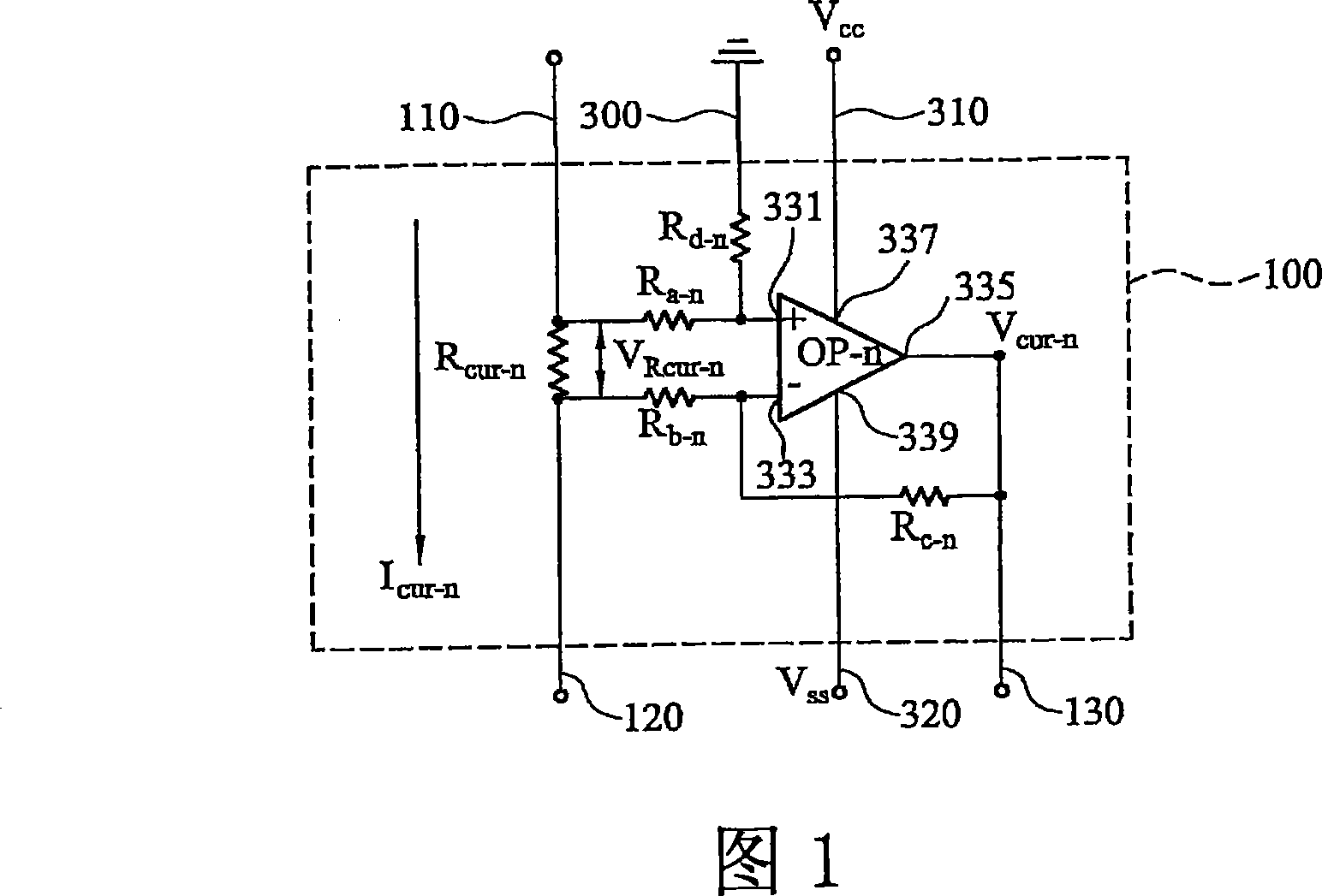
[0088] Please refer to FIG. 1 , which is a partial circuit diagram of a current feedback unit of an LED driving device with inflow current control capability according to an embodiment of the present invention. In this embodiment, the current feedback circuit for the LED driving device with inflow current control capability has a plurality of current feedback units {n}, n=1, 2, . . . , N, where N is a positive integer. In FIG. 1, the nth current feedback unit 100 representing a complex current feedback unit has an input terminal 110, a first output terminal 120, a second output terminal 130, a first reference line 310 for receiving a first supply voltage, a second The reference line 320 is used to receive the second supply voltage, the ...


PUM


Abstract

The present invention relates to a current feedback compensating circuit, a luminous diode driving device and a backlight system, and is suitable for the liquid crystal display device comprising a driving device, wherein the driving device has an inflow current control ability, the backlight system includes a light emitting diode array module, a current feedback circuit and a current compensating circuit; the light emitting diode array module comprises N lines of light emitting diode, and each line of light emitting diode comprises M light emitting diodes which are connected in serious; the current feedback circuit includes N current feedback unit and the current compensating circuit includes N current compensating units; the current feedback circuit and the current compensating circuit are all electrically coupled to the light emitting diode array module; when the backlight system is operated the current will run through a line of light emitting diode, a current feedback unit and a current compensating unit and generates an output electric voltage for comparing with the given direct current voltage and compensates the current according to the comparison result.

Description

technical field [0001] The present invention relates to a LED driving device, in particular to a LED driving device with current sink control for liquid crystal displays. Background technique [0002] A liquid crystal display (LCD) generally requires a cold cathode fluorescent lamp (CCFL) to provide a backlight for an image displayed on the LCD screen. In recent years, a light emitting diode (LED) array module has become a new backlight source, and has become more and more popular because it can make color images more vivid and bright. [0003] The LED array module is usually an I×J LED array, where I=1, 2, . . . , N, J=1, 2, . . . , M, M and N are positive integers. The LED array module has N rows of LEDs, and each row of LEDs has M LEDs respectively. Usually the LEDs in a row of LEDs are electrically connected in series. The anode of the first LED forms a first end of the row of LEDs, and the cathode of the first LED is electrically coupled to the anode of the second LE...

Claims


Application Information

Patent Timeline
Patent Type & Authority Applications(China)
IPC IPC(8): G09G3/34G09G3/36H05B37/02G02F1/133H03F3/45H01L33/00
CPCH05B33/0827H05B33/0857H05B45/46H05B45/20
Inventor 施鸿民李宗勋孙嘉宏林晃蒂
Owner AU OPTRONICS CORP
Features
  • R&D
  • Intellectual Property
  • Life Sciences
  • Materials
  • Tech Scout
  • Unparalleled Data Quality
  • Higher Quality Content
  • 60% Fewer Hallucinations
Learn More