Electric motor with permanent magnet excitation and rotor cooling

A technology for exciting motors and permanent magnets, applied in electromechanical devices, cooling/ventilation devices, magnetic circuits, etc., can solve problems such as complex implementation, and achieve the effects of improving motor efficiency, increasing magnetic flux, and high anti-demagnetization stability.

Inactive Publication Date: 2008-06-11
SIEMENS MOBILITY GMBH
View PDF0 Cites 10 Cited by
  • Summary
  • Abstract
  • Description
  • Claims
  • Application Information

AI Technical Summary

Problems solved by technology

[0005]Another way to remove heat from the rotor is to have forced air in the rotor, but this is more complicated to implement

Method used


Image

  • Electric motor with permanent magnet excitation and rotor cooling
  • Electric motor with permanent magnet excitation and rotor cooling
  • Electric motor with permanent magnet excitation and rotor cooling

Examples


Embodiment Construction

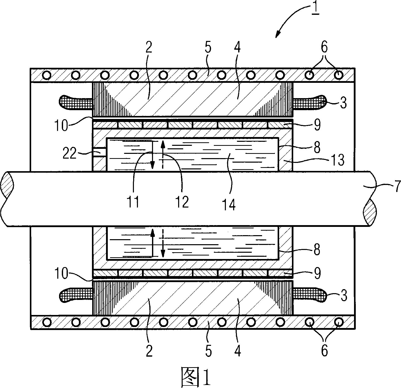
[0022] FIG. 1 shows a longitudinal section through a direct drive designed as a permanently excited synchronous machine 1 . This schematically represented permanent-magnet-excited synchronous machine 1 has a stator 2 consisting of laminated laminations 4 . Windings are arranged in slots (not shown in detail) of the stator 2 , which form end windings 3 on the end faces of the stator 2 . Most of the heat generated by these windings in the laminations 4 during the operation of the synchronous motor 1 is discharged from the stator through the heat dissipation sleeve 5 and the cooling medium (such as air or some kind of liquid) existing in the heat dissipation channel 6 . Wherein, the heat dissipation channel 6 extends around the stator 2 in a corrugated or helical shape.

[0023] The rotor 8 has a hollow shaft 13 shrink-fitted with the output drive shaft 7 . On the air-gap side of the permanent-magnet synchronous machine 1 , the rotor 8 has a plurality of permanent magnets 9 , w...


PUM


Abstract

The invention relates to an electric motor (1) with permanent magnet excitation, comprising a stator (2), a rotor (8), comprising a hollow shaft (13) on which the permanent magnets (9) are positioned. The hollow shaft (13) is sealed tight against an output shaft (7) at least at the end faces thereof and a suitable coolant is provided in the enclosed cavity (14) which, during operation of the electric motor, evaporates from the relatively hot hollow shaft in the region of the permanent magnets (9) and condenses in the region of the relatively cold output shaft (7) such as to introduce a radial and axial heat transport.

Description

technical field [0001] The invention relates to an electric machine with a stator and a rotor with a plurality of permanent magnets arranged on a hollow shaft. Background technique [0002] Losses in permanent magnet motors are mainly generated in the stator. The heat loss from the rotor is relatively small, but it must also be dissipated. A particularly important problem is the heating of the rotor in motors with a relatively large axial length, where the distance from the center of the rotor to the end face of the rotor is relatively long. [0003] The heat in the rotor reduces the flux, which adversely affects motor efficiency. [0004] It is known to dissipate the losses of the rotor via the supporting hollow shaft or the air gap between the rotor and the stator, or to suppress the reduction of the magnetic flux by a correspondingly costly choice of magnetic material. [0005] Another way to remove heat from the rotor is to have forced ventilation in the rotor, but th...

Claims


Application Information

Patent Timeline
Patent Type & Authority Applications(China)
IPC IPC(8): H02K9/20
CPCH02K1/32H02K1/278H02K9/22H02K9/20H02K9/227H02K9/225
Inventor 安德烈亚斯·乔克尔
Owner SIEMENS MOBILITY GMBH
Why Eureka
Try Eureka