

Main circuit structure for changing storage battery into charge and discharge
A discharge circuit, charge and discharge technology, applied in secondary battery charging/discharging, battery circuit devices, circuit devices, etc., can solve the problems of power factor reduction, grid pollution, power supply transformer heat increase, etc., to achieve harmonic Effects of pollution reduction and energy saving
- Summary
- Abstract
- Description
- Claims
- Application Information
AI Technical Summary
Problems solved by technology
Method used
Image

Examples
Embodiment Construction
[0014] Specific embodiments of the present invention will be described in detail below in conjunction with the accompanying drawings.
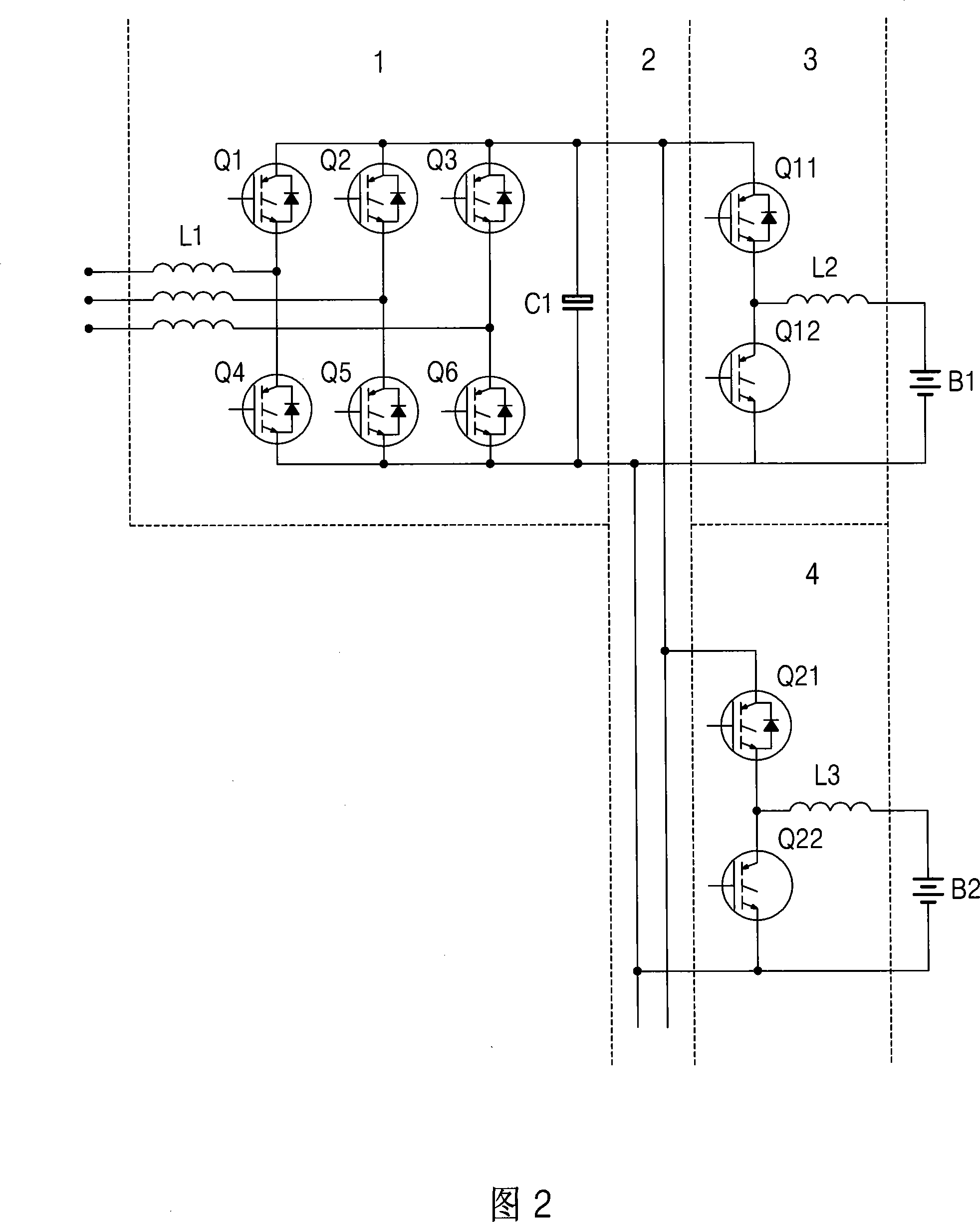
[0015] As shown in Figure 2, the storage battery of the present invention is formed into a charge-discharge main circuit structure, including: a reversible DC power supply 1 composed of six power transistors Q1-Q6, an input filter inductor L1 and an output filter capacitor C1. The power tube is a fully-controlled IGBT with a built-in reverse diode. Of course, the reverse diode can also be installed externally. The positive and negative poles of the power supply 1 are connected to the positive and negative DC buses in the DC bus unit 2 respectively. The charging and discharging units 3 and 4 are connected, and each charging and discharging unit includes a reversible charging circuit and a discharging circuit, wherein: the reversible charging circuit is mainly composed of an IGBT with a built-in reverse diode (in the charging and discharging unit...
PUM
 Abstract
Description
Claims
Application Information