Combined pressure-regulating valve

A pressure regulating valve, combined technology, applied in the direction of safety valve, balance valve, valve device, etc., can solve the problems affecting the performance and service life of the pressure regulating valve, the opening stroke of the valve is not large, unfavorable for production and debugging, etc., to achieve the goal of installation And the effect of convenient debugging, lower production cost, excellent pressure resistance and sealing performance

Inactive Publication Date: 2008-06-25
张家港市富瑞特种装备股份有限公司
View PDF0 Cites 7 Cited by
  • Summary
  • Abstract
  • Description
  • Claims
  • Application Information

AI Technical Summary

Problems solved by technology

[0005] It can be seen from the above that, 1. Because the diaphragms used in traditional booster and step-down regulators are generally made of copper or stainless steel, they are easily broken or wrinkled in actual use, which affects the pressure regulation. The performance and service life of the valve, and due to the limitation of the extensibility of the material itself, the opening stroke of the valve is not large
2. Since the boost regulator and the step-down regulator need to be configured simultaneously in the voltage stabilizing system, the pipeline will be very complicated, which is not conducive to production and debugging

Method used


Image

  • Combined pressure-regulating valve
  • Combined pressure-regulating valve
  • Combined pressure-regulating valve

Examples


Embodiment Construction

[0013] The present invention will be further described below in conjunction with the above-mentioned drawings and specific embodiments.

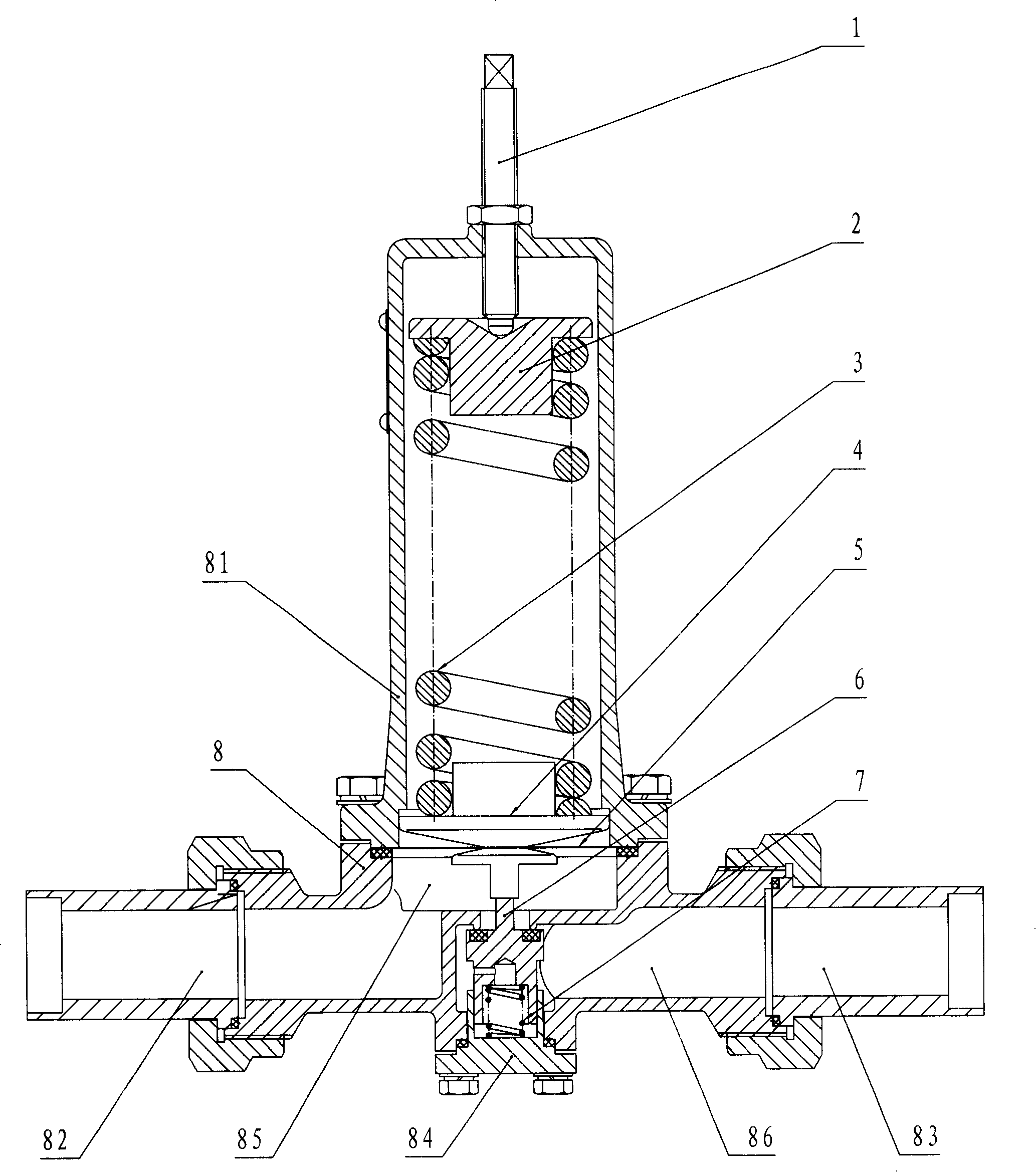
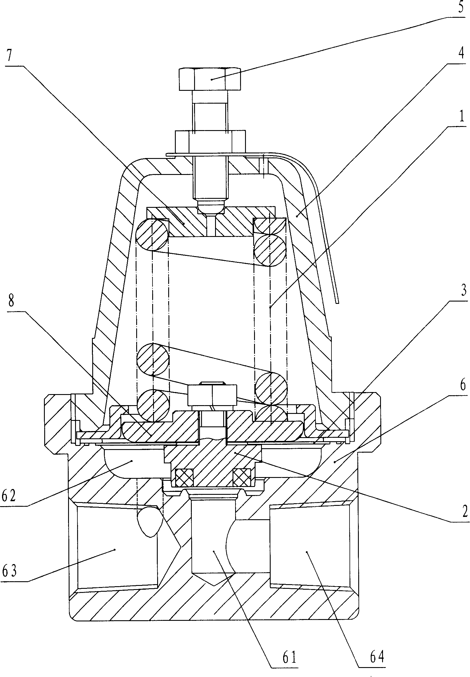
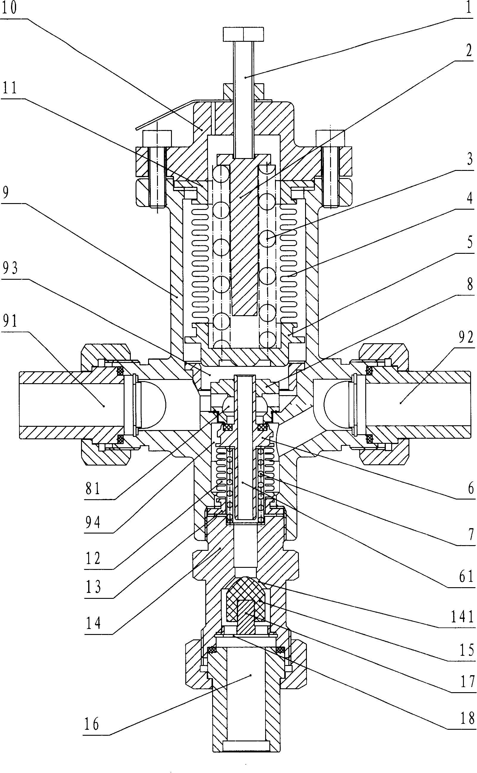
[0014] Such as image 3 As shown, the combined pressure regulating valve includes: a valve body 9, the two sides of the valve body 9 are respectively provided with an internal connection port 91 and an external pressure boost port 92, and the upper cover 10 of the valve body 9 is provided with Pressure regulating bolt 1; upper valve disc 5, upper bellows 4, upper connecting block 11, pressure regulating spring 3 and upper pressure block 2 are arranged in the upper valve cavity 93 of valve body 9, and pressure regulating bolt 1 passes through the upper pressure block 2 The top pressure is on the upper end of the pressure regulating spring 3, the lower end of the pressure regulating spring 3 is in contact with the upper valve disc 5, the upper valve disc 5 and the upper connecting block 11 are respectively connected with the two ends of the up...


PUM


Abstract

The invention discloses a combined type pressure regulating valve which simultaneously has pressure boosting and decreasing functions with longer service life. The invention comprises a valve body, wherein an internally communicated interface, an externally communicated pressure boosting interface and an externally communicated pressure decreasing interface are arranged on the valve body, a pressure regulating bolt is arranged on an upper cover of the valve body, an upper valve plate, an upper corrugated pipe, an upper connecting piece, a pressure regulating spring and an upper pressing block are arranged inside an upper valve cavity, and the internally communicated interface is communicated with the upper valve cavity; a valve seat is fixed in the upper valve cavity, the upper valve cavity and a lower valve cavity are communicated with each other through a valve seat cavity in the valve seat, and the lower valve cavity is communicated with the externally communicated pressure boosting interface; a lower valve plate, a lower corrugated pipe, a reset spring and a lower connecting piece are mainly arranged inside the lower valve cavity, the upper end of a passage in the lower valve plate is in seal contact with the upper valve plate, the lower end of the passage is communicated with the externally communicated pressure decreasing interface, and the lower valve plate can also block off the upper valve cavity and the lower valve cavity. The combined type pressure regulating valve which is widely applicable to the pressure stabilizing system of a low temperature pressure vessel can greatly simplify pipeline structure and improve production efficiency.

Description

technical field [0001] The invention relates to a combined pressure regulating valve with both pressure boosting and pressure reducing functions. Background technique [0002] On cryogenic pressure vessels used to store and transport liquid oxygen, liquid argon, liquid nitrogen and liquefied natural gas, etc., in order to stabilize the pressure in the cryogenic pressure vessel, it is usually used in conjunction with a voltage stabilizing system. The system usually includes a step-up system and a step-down system. In the step-up system and the step-down system, a step-up regulator and a step-down regulator are respectively used to achieve the purpose of boosting and reducing the pressure. [0003] The structure and working principle of the traditional boost pressure regulating valve are as follows: figure 1 As shown, the two sides of the valve body 8 are respectively provided with an internal connection port 82 and an external pressure boost port 83, and a pressure regulatin...

Claims


Application Information

Patent Timeline
Patent Type & Authority Applications(China)
IPC IPC(8): F16K17/04G05D16/06
Inventor 胡晨曦陈海涛
Owner 张家港市富瑞特种装备股份有限公司
Why Eureka
Try Eureka