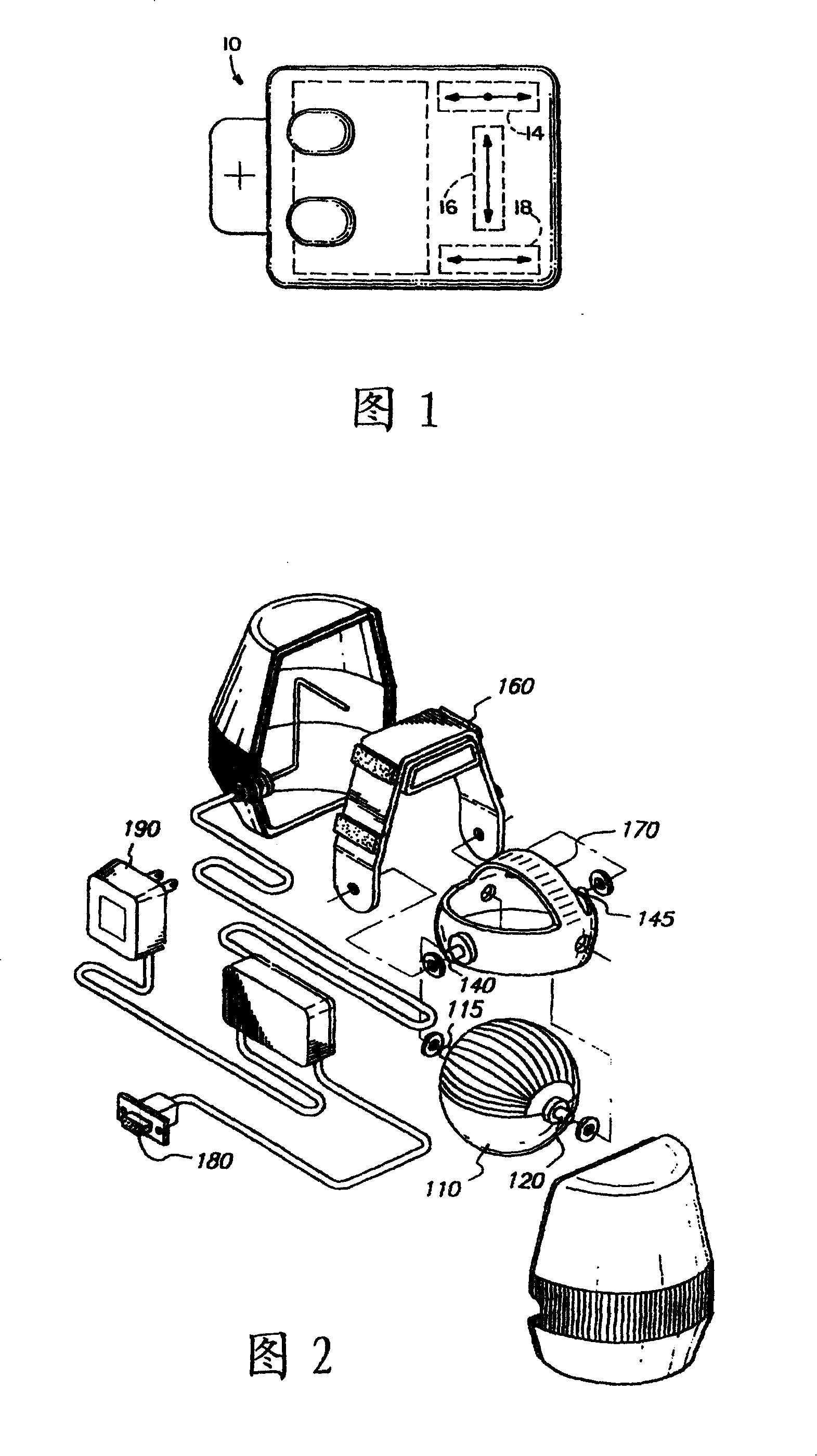
[0004] For patents, please refer to US Patent No. 4787051 "Inertial Mouse
System" shown in Figure 1, which discloses an inertial mouse 10, which mainly has an X-axis accelerometer 16, and the sensing direction is related to the described The X-axis accelerometer 16 is vertical and is divided into the Y-axis accelerometers 14,18 on both sides of the X-axis accelerometer 16, and the acceleration difference of the Y-axis accelerometers 14,18 is used to calculate the inertial mouse 10 The amount of rotation, in conjunction with the acceleration change sensed by the X-axis accelerometer 16, utilizes the
hardware algorithm again to digitize the curve trajectory of the inertial mouse 10 movement to input into the computer; the pure accelerometer coordinate input device, due to the rotation The amount is calculated indirectly by the difference between the two accelerometers, so the error is huge, and because it only has X-axis and Y-axis accelerometers, it can only be operated on a plane
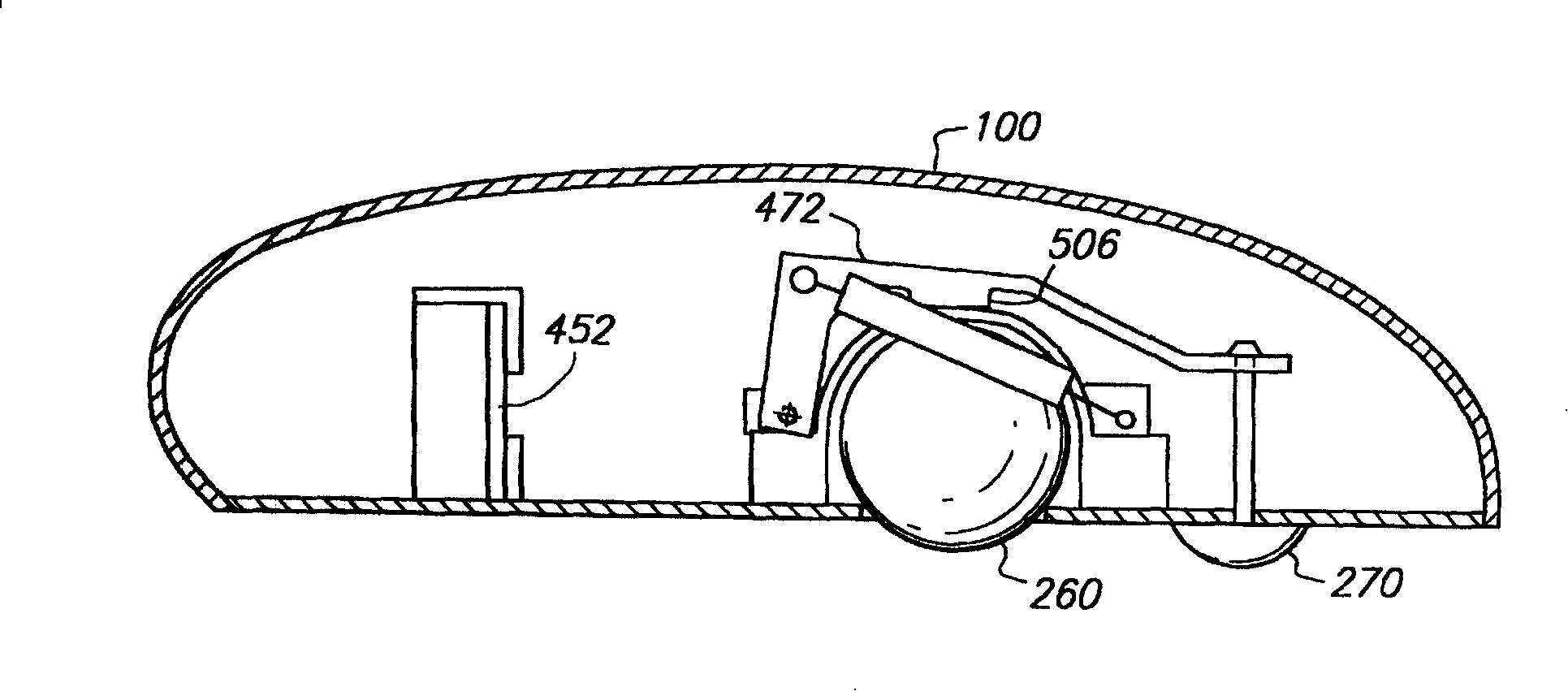
[0005] Please refer to the U.S. Patent No. 5,898,421 "Gyroscopic pointer and method" shown in Fig. 2, which discloses an indicator, which can drive a mechanical gyroscope 110 to rotate with an external power supply 190, and the mechanical gyroscope 110 is pivotally connected in an inner frame 170 by means of a set of cardan shafts 115, 120, and the inner frame 170 relies on another set of cardan shafts 140, 145 is pivotally connected in an outer frame 160. When the device is operated in
free space, the rotation amount of the gyroscope 110 can be corresponding to the cursor X, Y of the
display device by means of the computer connection head 180 The amount of two-axis movement; the above-mentioned indicator is only suitable for
free space because it uses a pure gyroscope to input coordinates, and cannot be used on a plane. Moreover, the mechanical gyroscope is bulky and has a high error value
[0006] see again image 3 As shown in US Patent No. 5825350 "Electronic pointing apparatus and method", the case discloses a
pointing device 100 that can operate in a plane and in space. It is provided with a rolling ball 260 inside the
pointing device 100, and The internal circuit board 452 is provided with a gyroscope circuit, and a lever 472 is linked by a
piston 270. When the indicating device 100 is pressed on a plane and used (that is, when used as a mouse), the
piston 270 The lever 472 can be pushed up so that the rolling ball 260 can move freely. When the indicating device 100 is lifted, the
piston 270 can naturally pull the lever 472 down. , so that the protrusion 506 arranged at the bottom of the lever 472 is pressed against the rolling ball 260 to
restrict the movement of the rolling ball 260. At this time, the indicating device 100 can be used as an indicator, By virtue of the circuit board 452 provided with the gyroscope circuit, the amount of movement of the
pointing device 100 can be detected and corresponded to the cursor of the
display device; however, the lever 472 and the bump 506 cannot really suppress the The above-mentioned rolling ball 260, when the human
hand shakes the above-mentioned pointing device 100 in space, it is very easy to cause the above-mentioned rolling ball 260 to move or roll unexpectedly, thereby generating unnecessary moving signals and affecting coordinate input. Therefore, The described structure has not been implemented or applied in the
consumer market
[0007] Currently available on the market with image 3 The pointing device shown is a similar
consumer product, which combines a gyroscope in an
optical mouse. Although the
optical sensing device can avoid the problem of unexpected movement of the rolling ball, however, whether it is a rolling ball or
optical sensing, The rolling ball responsible for planar operation, the
optical sensing and the gyroscope circuit responsible for space operation are not related to each other. The above-mentioned similar structure only provides a shared housing for accommodating the two
operation mode devices. Not only the basic functions are not increased, but the overall device is complicated and bulky, and the weight increases
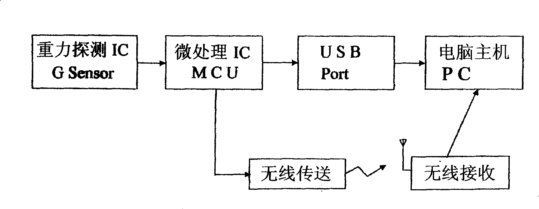
[0008] Another example Figure 4 As shown, the Taiwan Province of China
Patent Application No. 90221010 "Gravity Mouse", which uses a gravity detection IC to measure the
potential energy of an object, converts the
potential energy into a
signal generated by
kinetic energy, and transmits it to the
microprocessor IC for calculation. The
microprocessor IC can detect the time of the gravity detection IC movement, and receive the acceleration value generated by the gravity detection IC movement, calculate and convert it into an actual movement unit, and transmit it to the computer host to control the direction of the screen cursor; The main calculation means of the case is that when the mouse moves in space, the accelerometers with two or more axes are used to perform integral calculations to control the movement of the cursor. The biggest
disadvantage of the above method is that it will generate cumulative errors, resulting in
distortion of the cursor positioning
[0009] According to the above, it can be known how to have a plane / space operation function that is not limited by the operating space, can overcome the coordinate
distortion and large error of the existing pure accelerometer or pure gyroscope coordinate input device, and at the same time can compensate Coordinate input devices that cause errors caused by involuntary manual operation are an urgent issue for relevant industry players to solve

