
Method for anti-self excitation of straight amplification station system

A repeater and self-excited technology, which is applied in the transmission system, baseband system components, radio relay system, etc., can solve the problems of base station control channel blocking, base station paralysis, and affecting the coverage of the repeater system. System gain, effect of increasing coverage

Inactive Publication Date: 2008-06-25
COMBA TELECOM TECH (GUANGZHOU) CO LTD
View PDF0 Cites 31 Cited by
  • Summary
  • Abstract
  • Description
  • Claims
  • Application Information

AI Technical Summary

Problems solved by technology

[0003] However, in practical applications, since the front and rear antennas of the same-frequency wireless repeater are installed near each other, coupling will inevitably occur. If the system gain is too large, it is greater than the isolation between the front and rear antennas of the repeater. , the repeater will have self-oscillation, causing the control channel of the base station to be blocked, and even cause the base station to be paralyzed
[0004]In the same-frequency wireless repeater system, the interference source formed by the feedback signal will lead to the decline of the performance of the receiver system, and then make the same-frequency wireless repeater The system gain of the station is usually about 10-15dB lower than the isolation between the transmitting antenna and the receiving antenna, which will affect the coverage of the repeater system
In order to increase the system gain of the same-frequency wireless repeater, it is necessary to increase the isolation between the transmitting and receiving antennas, which forms a contradiction with the above, and is usually difficult to achieve in engineering applications

Method used


Image

  • Method for anti-self excitation of straight amplification station system
  • Method for anti-self excitation of straight amplification station system
  • Method for anti-self excitation of straight amplification station system

Examples


Embodiment Construction

[0044] Below in conjunction with accompanying drawing and embodiment the present invention will be further described:

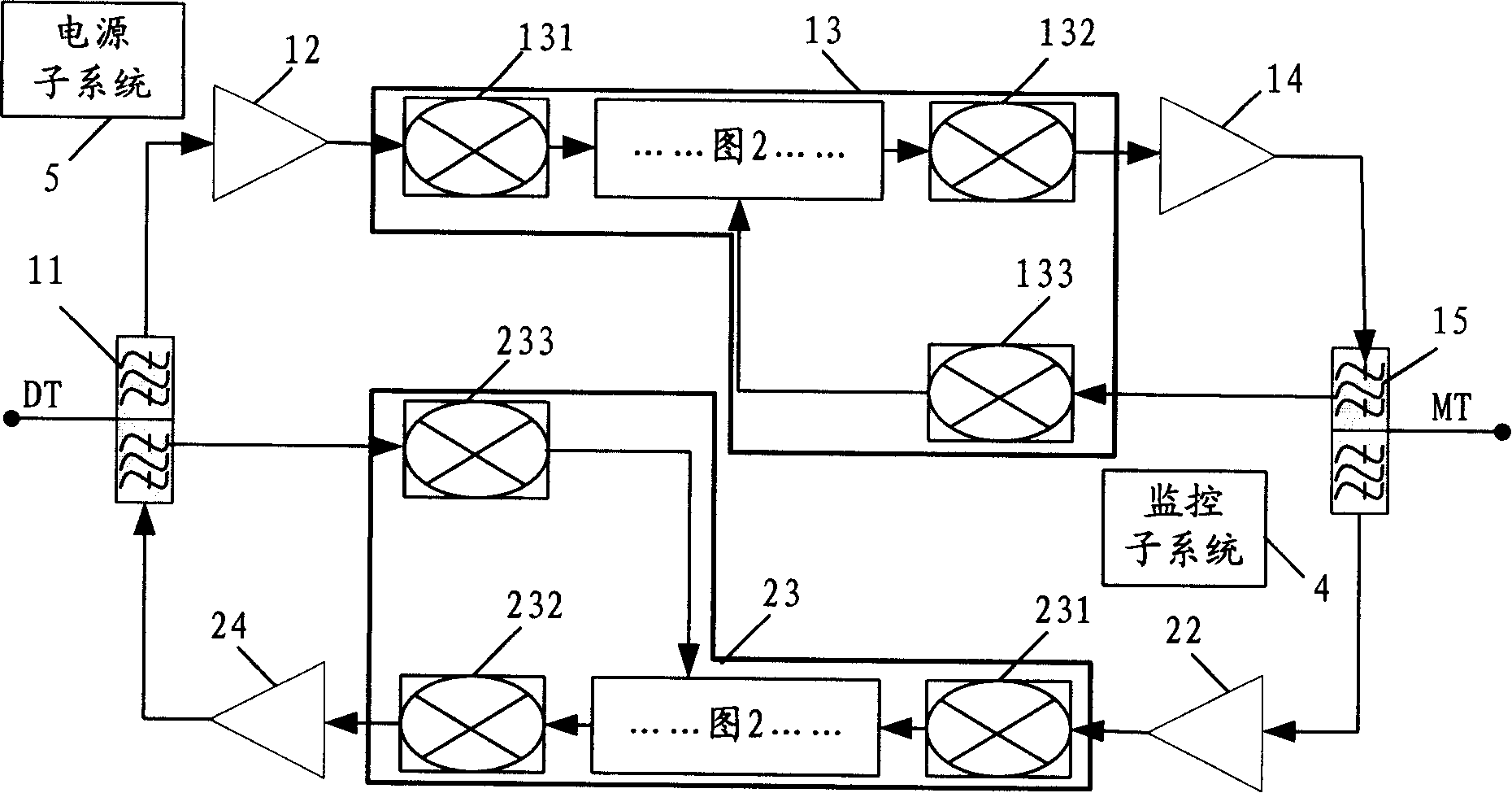
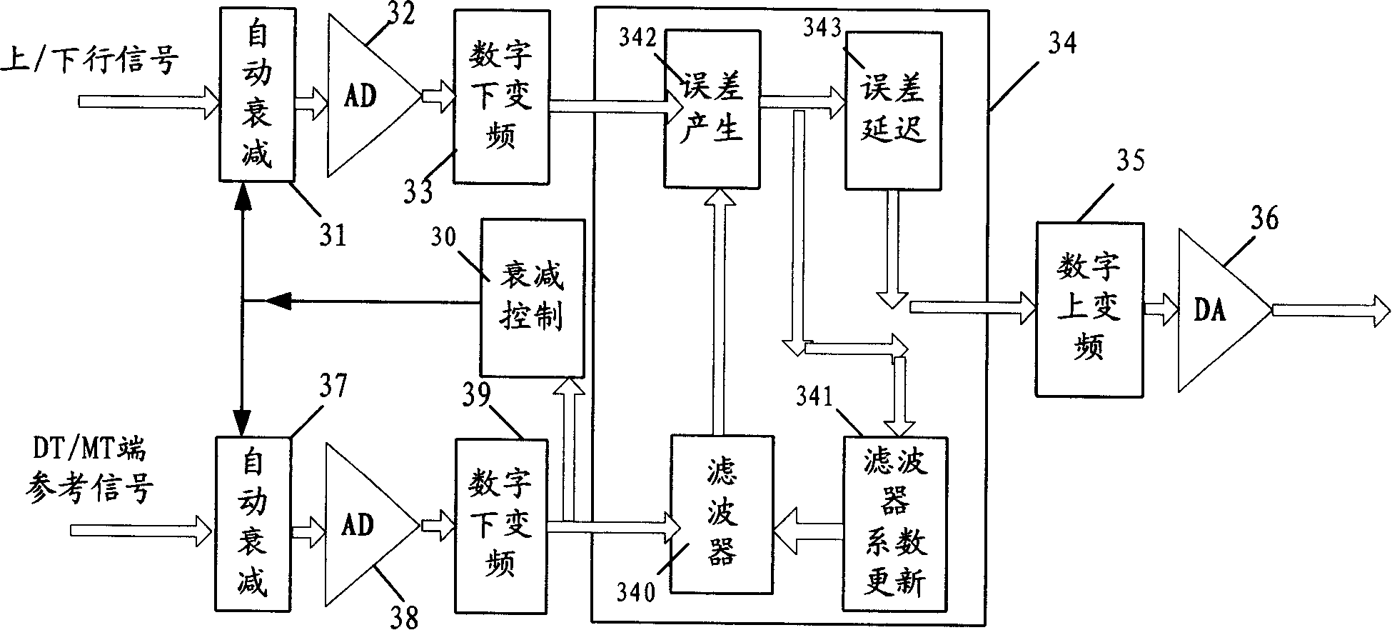
[0045] Please combine figure 1 and figure 2 , figure 1 For applying the block diagram of the same-frequency wireless repeater of the repeater system anti-self-excitation method of the present invention, figure 2 It is a functional block diagram when the present invention is realized by hardware, but the analog down-converter is in figure 1 shown in .

[0046] figure 1 Among them, the downlink is composed of the DT end duplexer 11, the downlink amplification modules 12, 14, the downlink anti-self-excitation module 13, and the MT end duplexer 15, and the MT end duplexer 15, the uplink amplification modules 22, 24, The uplink anti-self-excitation module 23 and the DT-side duplexer 11 together constitute an uplink.

[0047] Wherein, the uplink and downlink amplifying modules 22, 24, 12, 14 can be low noise amplifying modules 12, 22 or power amplifying mod...


PUM


Abstract

The invention provides an anti-self-excitation method in a repeater system, and is applicable to the uplink and the downlink of a co-frequency wireless repeater. The method includes the following steps of: (1) taking a RF signal to be outputted in the coupling circuit in the uplink or the downlink in the repeater as a reference signal; (2) down converting the single in an affiliated link and the reference signal from a RF signal format to a baseband signal format; (3) eliminating the self-excitation element of the link signal in the affiliated link on the basis of the reference signal in the baseband level, for outputting a multi-carrier wave baseband signal of which the self-excitation interference signal is eliminated; (4) up converting the multi-carrier wave baseband signal into the RF signal and feeding the RF signal into the uplink or the downlink. The invention can cause the co-frequency wireless repeater to eliminate the self-excitation interference produced by the feedback signal effectively and adaptively, can lessen the requirement of the isolation degree of forward and backward antennas, can improve the gain of the system, can enlarge the coverage of the repeater, and is applicable for GSM / CDMA / CDMA2000 / WCDMA, and other systems.

Description

【Technical field】 [0001] The invention relates to the field of mobile communication, in particular to a repeater system anti-self-excitation method in same-frequency wireless repeaters. 【Background technique】 [0002] The same-frequency wireless repeater usually uses a duplexer to switch between the uplink and downlink, uses the forward antenna to receive the downlink signal of the base station, amplifies the useful signal through a low-noise amplifier, and then uses a narrowband filter to further filter the downlink signal with a power amplifier. The power is amplified and transmitted to the mobile station by the backward antenna; at the same time, the uplink signal of the mobile station is received by the backward antenna, and transmitted to the base station through a low noise amplifier, a narrowband filter, and a power amplifier. Its advantages are: to expand the coverage area at a cost far lower than the base station investment, the installation conditions are simple, a...

Claims


Application Information

Patent Timeline
IPC IPC(8): H04B7/14H04Q7/30H04L25/03H04B15/00
Inventor 施英罗漫江刘志敏赖文强
Owner COMBA TELECOM TECH (GUANGZHOU) CO LTD
Learn More