Steel bar hydraulic pressure cutting machine

A cutting machine, hydraulic technology, applied in the direction of instruments, electrical digital data processing, data processing input/output process, etc., can solve the problems of fire hazards, sparks splashing, dust and noise, etc., and achieve safe and convenient cutting. Dust, avoiding the effect of side thrust

Inactive Publication Date: 2008-07-02
周才森
View PDF0 Cites 6 Cited by
  • Summary
  • Abstract
  • Description
  • Claims
  • Application Information

AI Technical Summary

Problems solved by technology

When in use, put the steel bar flat on the workbench, start the motor, drive the saw blade to rotate at high speed, press down the movable arm to make the cutting edge of the saw blade contact with the steel bar, and cut off the steel bar in high-speed friction; the disadvantage of this device is: When cutting, sparks fly, there is a fire hazard, and there is a lot of dust and noise during cutting

Method used


Image

  • Steel bar hydraulic pressure cutting machine

Examples


Embodiment Construction

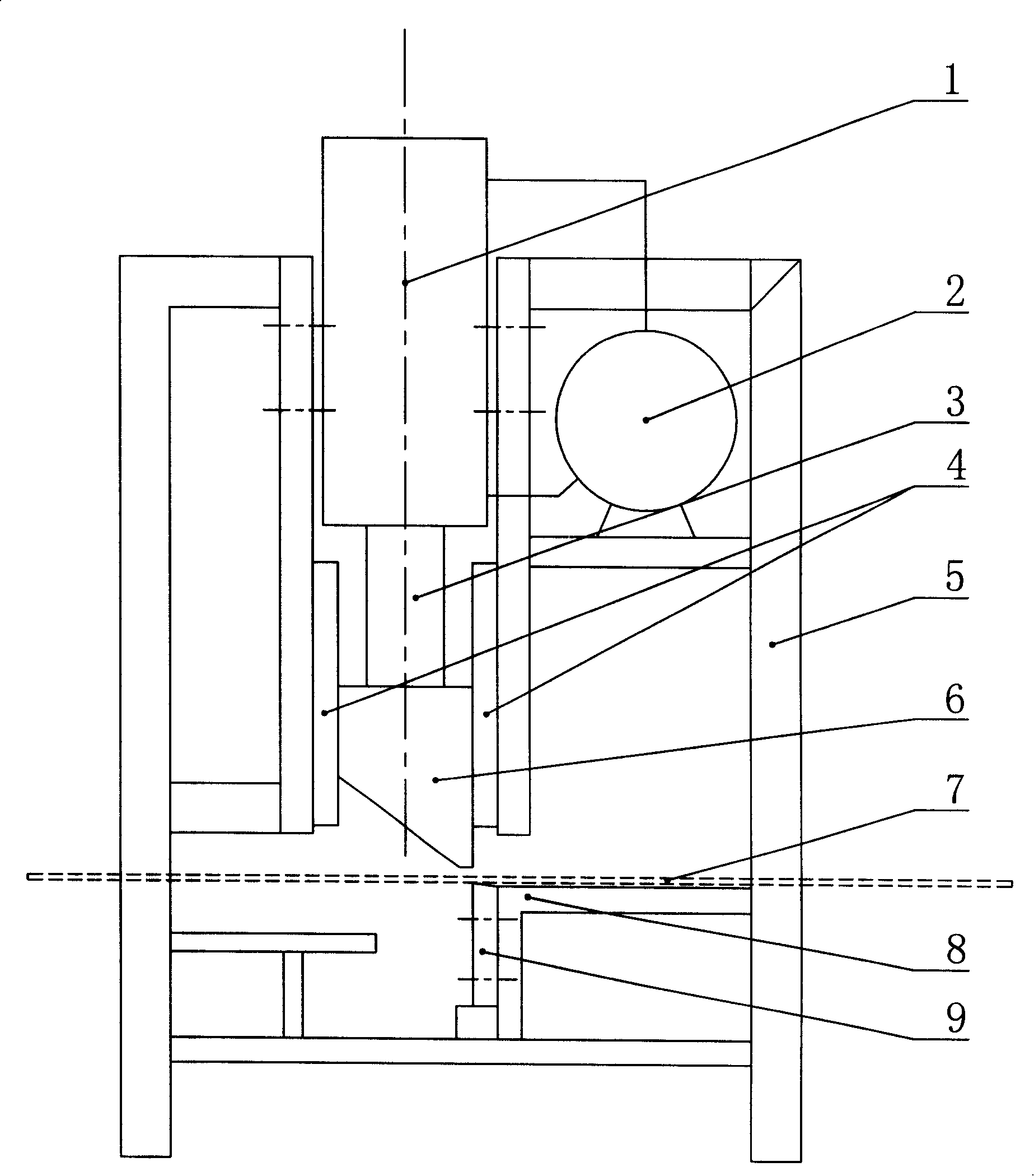
[0009] As shown in the figure, it is a hydraulic cutting machine for steel bars. Its body 5 is provided with a workbench 8. An oil cylinder is vertically arranged on the body 5 above the workbench 8. A hydraulic oil pump 2 for supplying oil to both ends of the hydraulic cylinder 1 is arranged on the body 5. , the piston rod 3 of the oil cylinder stretches out from the lower end of the oil cylinder, the extended end of the piston rod 3 is connected with an upper cutter 6, and the two sides of the upper cutter 6 are vertically provided with guide plates 4, and the lower part of the upper cutter 6 is provided with an upper cutter. The following cutting knife 9 that knife 6 cooperates, following cutting knife 9 is fixed on the body 5 of workbench 8 lower sides.

[0010] When working, supplying oil to the hydraulic cylinder 1 can drive the piston in the hydraulic cylinder 1 to move upwards or downwards. Correspondingly, the upper cutter 6 at the end of the piston rod 3 can reciproca...


PUM


Abstract

The invention discloses a hydraulic bar cutting machine, pertaining to the field of bar cutting equipment in construction, which comprises a body provided with a working table, a cylinder vertically positioned at the body over the working table, a piston rod of the cylinder extending from the lower end of the cylinder, an upper cutter connected with the extending end of the piston rod, a guiding plate vertically arranged at the two sides of the upper cutter, a lower cutter which is matched with the upper cutter, arranged below the upper cutter and fixed on the body below the working table. When in working, hydraulic cylinder is supplied with oil and the piston rod drives the upper cutter to perform vertical reciprocating motion; the bar is put on the working table, thus leading the position needing cutting to be aligned with the matching position of the upper cutter and the lower cutter and to be cut by the shearing motion of the upper cutter and the lower cutter; the guiding plate can offset lateral thrust generated during the shearing motion so as to prevent the piston and the piston rod from lateral thrust. No dust, noise and spark exist during the process of bar cutting and the cutting is safe and convenient; therefore, the invention can be applied to construction.

Description

technical field [0001] The invention relates to a building construction tool, in particular to a device for cutting steel bars in building construction. Background technique [0002] In the building construction process, reinforced concrete structure is widely used. Before pouring concrete, it needs to be tied into a skeleton with steel bars. The commercially available steel bars are all standard specifications. When in use, on-site operations are required to cut the steel bars into required lengths; There is a cutting machine for cutting steel bars, which mainly includes a fuselage with a workbench and a movable arm that can move up and down. A motor is fixed on the movable arm, and the shaft end of the motor is connected with a Cutting saw blade, the cutting saw blade is located above the workbench. When in use, put the steel bar flat on the workbench, start the motor, drive the saw blade to rotate at high speed, press down the movable arm to make the cutting edge of the ...

Claims


Application Information

Patent Timeline
Patent Type & Authority Applications(China)
IPC IPC(8): B21F11/00G06F3/0354
CPCG06F3/03543
Inventor 周才森
Owner 周才森
Why Eureka
Try Eureka