Heat exchange method in hydrocarbon oil conversion process and hydrocarbon oil conversion method

A technology of conversion process and thermal method, which is applied in the fields of heat exchange and hydrocarbon oil conversion in the process of hydrocarbon oil conversion, can solve problems such as low heat exchange efficiency, achieve the effects of small heat loss, reduce catalyst consumption, and improve heat exchange efficiency

Active Publication Date: 2008-07-02
CHINA PETROLEUM & CHEM CORP +1
View PDF1 Cites 2 Cited by
  • Summary
  • Abstract
  • Description
  • Claims
  • Application Information

AI Technical Summary

Problems solved by technology

[0006] The object of the present invention is to provide a heat exchange method in the hydrocarbon oil conversion process that can improve the heat exchange efficiency in order to overcome the shortcomings of the low heat exchange efficiency of the existing heat exchange method in the hydrocarbon oil conversion process

Method used


Image

  • Heat exchange method in hydrocarbon oil conversion process and hydrocarbon oil conversion method
  • Heat exchange method in hydrocarbon oil conversion process and hydrocarbon oil conversion method
  • Heat exchange method in hydrocarbon oil conversion process and hydrocarbon oil conversion method

Examples


Embodiment 1

[0041] This example is used to illustrate the heat exchange method in the hydrocarbon oil conversion process provided by the present invention.

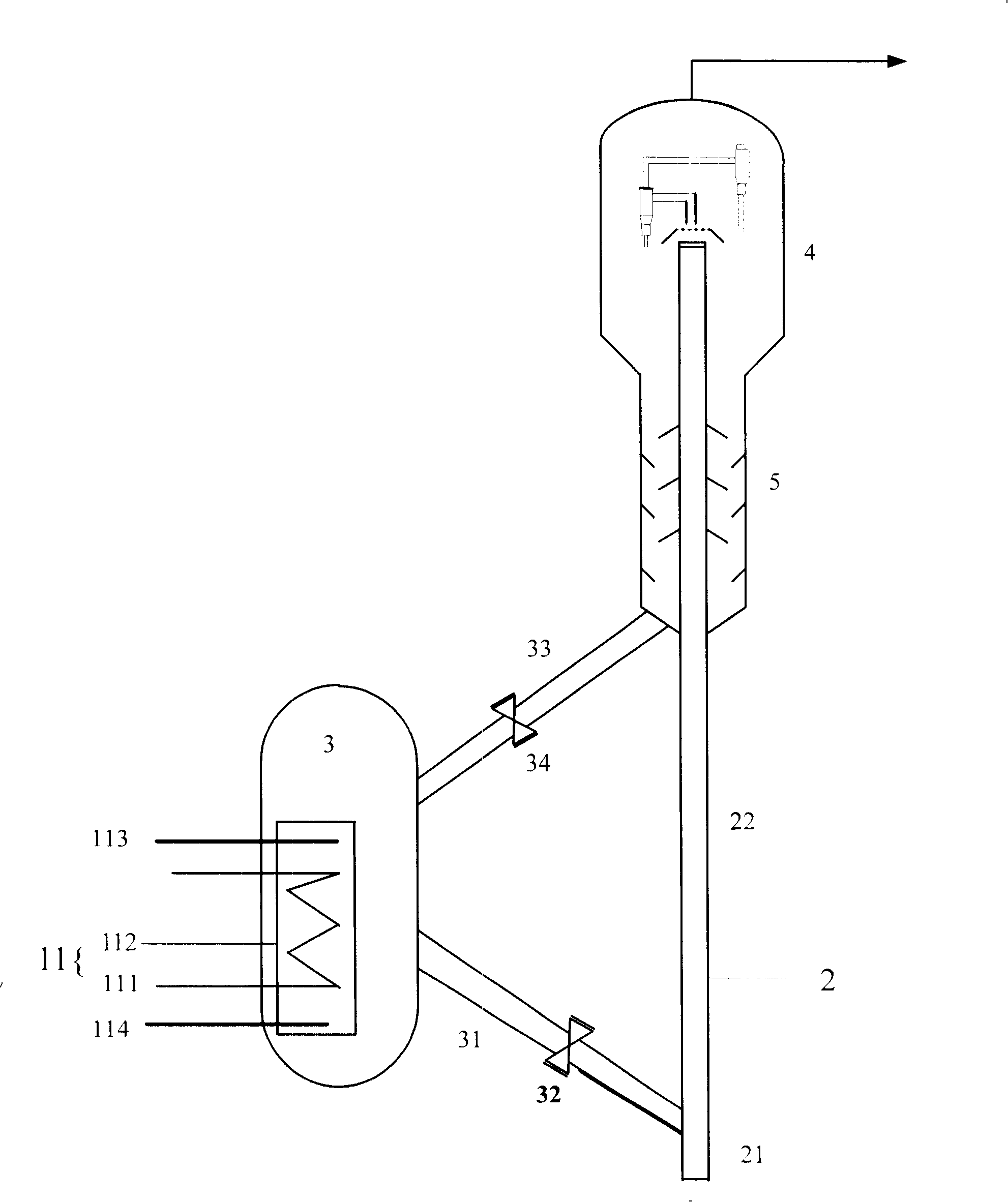
[0042] like figure 1 As shown, the shell-and-tube heat exchanger 11 is located in the regenerator 3, and 3 kg of hydrocarbon oil with a temperature of 160° C. enters the heat exchanger pipe 111 of the shell-and-tube heat exchanger 11, and the temperature in the regenerator 3 is 20 kg of regenerated catalyst at 685°C for heat exchange. The space between the heat exchanger shell 112 and the heat exchanger pipe 111 of the shell-and-tube heat exchanger 11 is filled with water vapor as a heat transfer medium, and the weight ratio of water vapor to hydrocarbon oil is 0.9:1. After 15 minutes of heat exchange, the temperature of the hydrocarbon oil after heat exchange was 280°C, and the temperature of the regenerated catalyst after heat exchange was 640°C.

Embodiment 2

[0047] This example is used to illustrate the hydrocarbon oil conversion method provided by the present invention.

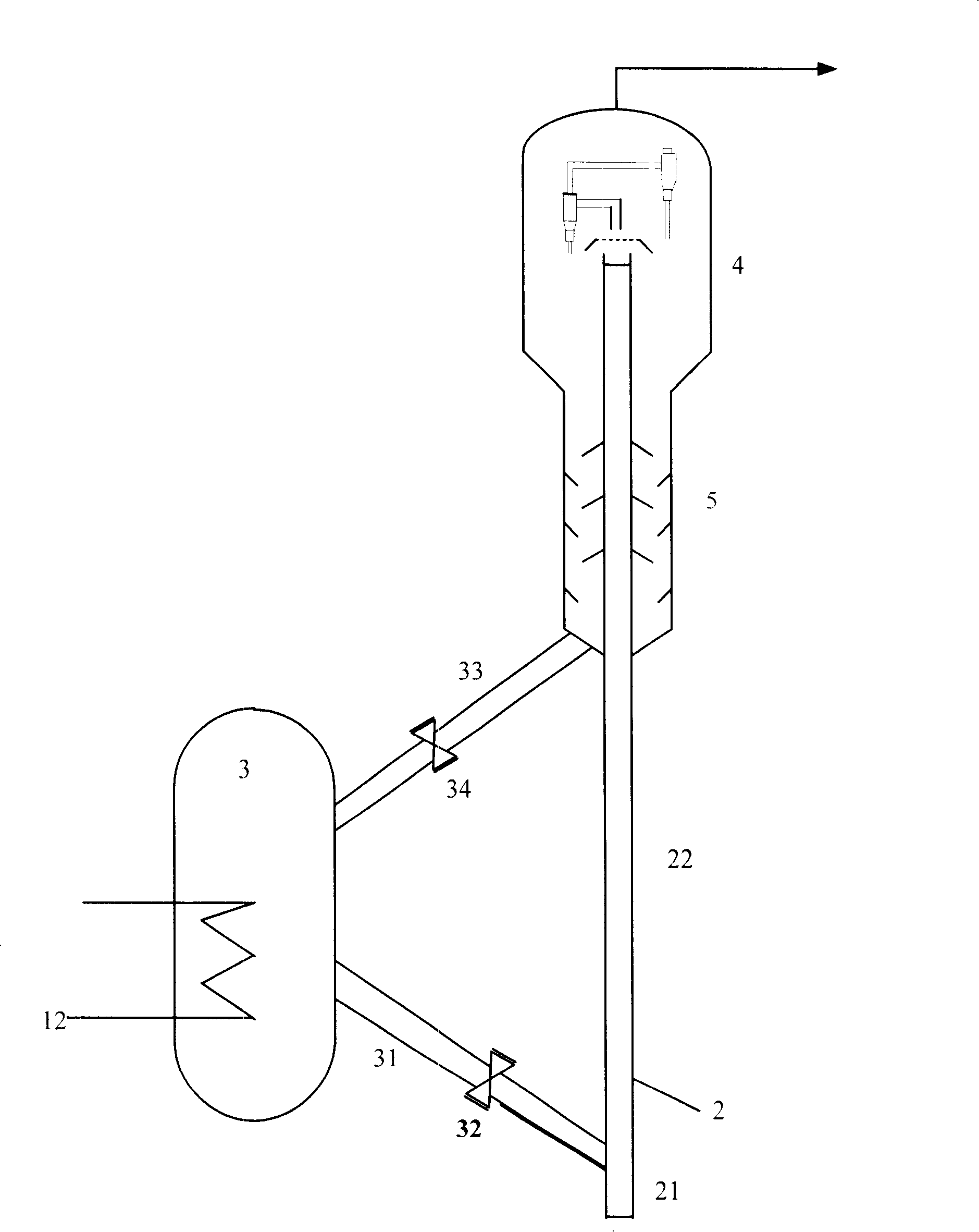
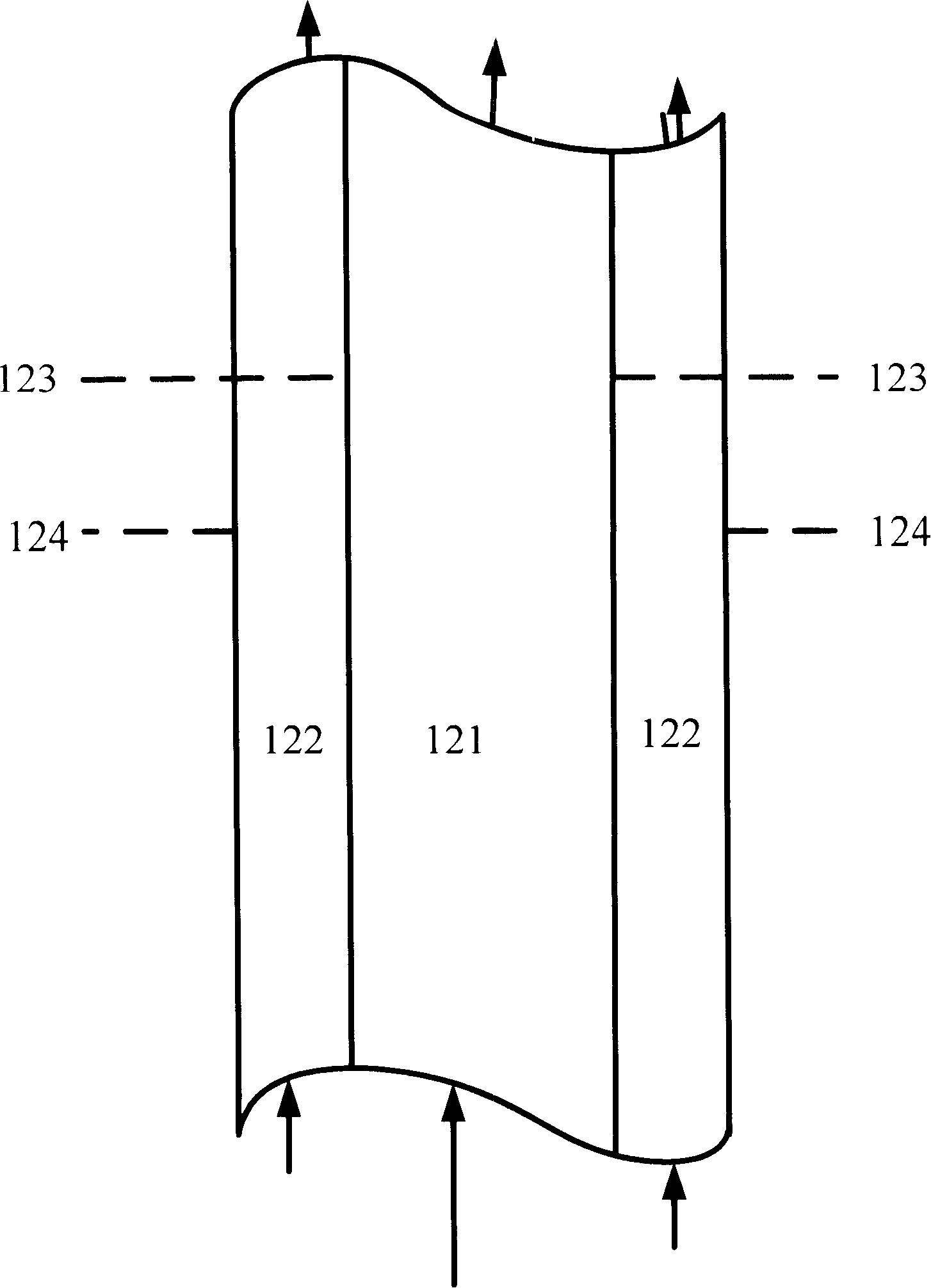
[0048] like figure 2 and image 3 As shown, the hydrocarbon oil with a temperature of 160°C enters the inner pipe 121 of the heat exchange pipe 12, and exchanges heat with the regenerated catalyst at a temperature of 685°C in the regenerator, and the outer pipe of the heat exchange pipe 12 is filled with water vapor as Heat transfer medium, the weight ratio of water vapor and hydrocarbon oil is 1.2:1. The temperature of the hydrocarbon oil after heat exchange is 255°C, and it enters the reactor 2. The temperature of the regenerated catalyst after heat exchange is 635° C., and enters the reactor 2 from the regenerated catalyst delivery pipeline 31 through the regenerated slide valve 32 .

[0049] The regenerated catalyst after heat exchange contacts with the hydrocarbon oil after heat exchange in the reaction section 22 of the reactor 2 to carry out catalytic...


PUM


Abstract

A heat exchanging method in hydrocarbon oil transforming process comprises the step of exchanging heat of hydrocarbon oil with that of a regeneration catalyst in a regenerator by a heat exchanger, wherein the heat exchanger is positioned in the regenerator. The invention also provides a hydrocarbon oil transforming method including the heat exchanging method. According to the heat exchanging method in the hydrocarbon oil transforming process in the invention, the heat exchanger is positioned in the regenerator to exchange the heat of the high-temperature regeneration catalyst with that of the raw material oil in the regenerator, so that the high-temperature regenerator catalyst has less heat loss and that the amount of the raw material oil that can be heated by reducing a certain temperature of the regeneration catalyst per unit is improved, thus improving the heat exchanging efficiency. Additionally, the heat exchanging method of the method can simultaneously perform the function of lowering temperature in the regenerator and preventing the catalyst from hydrothermal deactivation due to overhigh temperature, thus reducing the amount of fresh catalyst to be supplemented and reducing the catalyst consumption. The hydrocarbon oil transforming method of the invention can reduce the yields of dry gas and coke and improve the yield of liquid products.

Description

technical field [0001] The invention relates to a heat exchange method and a hydrocarbon oil conversion method in a hydrocarbon oil conversion process. Background technique [0002] Catalytic cracking is one of the important means of petroleum secondary processing, which is used to produce gasoline, diesel, liquefied petroleum gas, etc. from heavy hydrocarbon oil. Generally speaking, the hydrocarbon oil cracking method comprises that under cracking conditions, the hydrocarbon oil is contacted with a catalyst in a reactor, and the hydrocarbon oil generates cracked products through a cracking reaction under the action of the catalyst (the cracked products include light oil products, heavy At the same time, the coke generated by the reaction is deposited on the catalyst, and the catalyst deposited with coke needs to be regenerated before it can be used in the catalytic cracking reaction again, so it is generally called a standby catalyst; the standby catalyst and the cracked pr...

Claims


Application Information

Patent Timeline
Patent Type & Authority Applications(China)
IPC IPC(8): C10G11/05C10G11/00
Inventor 侯典国毛安国张久顺谢朝钢
Owner CHINA PETROLEUM & CHEM CORP
Why Eureka
Try Eureka