A descending catalytic cracking unit

A catalytic cracking unit and catalyst technology, applied in the field of catalytic cracking, can solve the problems of deteriorated product distribution, hydrothermal deactivation of catalysts, and low stripping efficiency in the stripping section, so as to improve the coking intensity and coking efficiency, reduce dry Gas and coke yields, the effect of promoting catalytic cracking reactions

Active Publication Date: 2016-04-13
CHINA PETROCHEMICAL CORP +1
View PDF6 Cites 0 Cited by
  • Summary
  • Abstract
  • Description
  • Claims
  • Application Information

AI Technical Summary

Problems solved by technology

In the above-mentioned conventional catalytic cracking unit, there are the following disadvantages: first, the temperature of the regenerated catalyst cannot be flexibly controlled, and the catalyst at the regenerated temperature is generally higher than 650°C, and the oil agent contact temperature in the riser reactor is relatively high, and the relatively high The oil agent contact temperature makes the degree of thermal cracking reaction higher, while the degree of catalytic cracking reaction is lower, resulting in higher yield of dry gas and coke, and lower total liquid yield (total liquid yield refers to liquefied gas yield, The sum of gasoline yield and diesel yield); due to the high regenerated catalyst temperature, limited by the heat balance of the device, the agent-oil ratio of the heavy oil riser reactor is relatively small, generally 5-8 (the agent-oil ratio of the riser reactor The oil ratio is the ratio of the weight circulation of the catalyst in the riser reactor to the weight flow rate of the heavy oil riser reactor feed), so that the number of active centers contacted by the feed oil per unit weight is small, which also inhibits the catalyst The cracking reaction proceeds
Second, due to the length of the riser reactor, the reaction time of the raw material is longer (generally about 4s), and the longer reaction time increases the single-pass conversion rate of the raw material and also intensifies the secondary reaction of the cracked product of the raw material , so that the yield of cracked gas (the sum of yields of dry gas and liquefied gas) is higher, the yield of gasoline and diesel fractions is lower, and the cetane number of catalytic diesel oil is lower, so it is not suitable as a vehicle fuel
Third, due to the upward movement of the catalyst in the riser reactor against the gravitational field, the coking catalyst slips and back-mixes. On the upper part of the feed nozzle of the riser reactor, the coking catalyst that slips, the atomized raw material and the primary cracking product Re-contacting reactions, thereby deteriorating product distribution and reducing product selectivity of catalysts for feedstock cracking
Fourth, due to the relatively low coking intensity of the turbulent bed regenerator, the catalyst storage in the regenerator is relatively high and the catalyst stays in the regenerator for a long time, resulting in serious hydrothermal deactivation of the catalyst
Fifth, the stripping efficiency in the stripping section is low, resulting in more strippable coke
Sixth, catalytic gasoline cannot be modified independently, and its quality is low
However, this technology has the following disadvantages: First, the advantages of reducing the contact temperature of oil agent in the riser and increasing the ratio of agent to oil can only be reflected in the combination of the light hydrocarbon riser standby catalyst and the regenerated catalyst to reduce the temperature. Second, because the catalytic cracking reactor used in this technology is a traditional riser reactor, it still shows that the product distribution is relatively poor due to the long reaction time and catalyst back-mixing; the second Third, because the technology uses a traditional turbulent bed regenerator, there is a problem of low coking efficiency; fourth, due to the use of conventional stripping methods, the increase in catalyst circulation will have an adverse effect on the stripping effect
However, this technology has the following disadvantages: First, due to the use of traditional riser reactors, it is impossible to achieve short reaction times for raw materials and overcome catalyst backmixing
Second, the process and operation are complicated, and it is difficult to implement in engineering
Third, the use of a single reactor cannot achieve separate upgrading of catalytic gasoline
However, this technology also has the following disadvantages: First, due to the use of a conventional turbulent bed regenerator, its coking efficiency is low
Second, the unborn catalyst participates in the reaction, which reduces the average activity of the mixed catalyst, and will inevitably have an adverse effect on product distribution and product properties
Third, the process and operation are more complicated
Fourth, the use of a single reactor cannot achieve separate modification of gasoline
However, this technology still has the following disadvantages: First, the temperature of the regenerated catalyst cannot be flexibly controlled, and the operation of "low temperature contact, large agent-to-oil ratio" cannot be realized, which will adversely affect product distribution and product properties
Second, the inertia separator used at the end of the downcomer reactor is not completely separated from the oil agent, and part of the oil and gas reacts for a long time
Third, the use of a single reactor cannot achieve separate upgrading of gasoline

Method used


Image

  • A descending catalytic cracking unit
  • A descending catalytic cracking unit
  • A descending catalytic cracking unit

Examples


Embodiment 1

[0120] Embodiment 1, comparative example

[0121] Experiments were carried out on a conventional double-riser catalytic cracking pilot plant. The heavy oil riser reactor processes Daqing atmospheric residue, and the light hydrocarbon riser reactor processes the catalytic gasoline produced by the heavy oil riser reactor. The commercially available CC-20D catalytic cracking industrial equilibrium catalyst is used as the catalyst.

[0122] The design capacity of the heavy oil riser reactor is 60kg / d, simulating the full back refining operation, the heavy oil raw material is mixed with the recycle oil and enters the heavy oil riser reactor through the feed nozzle; the design capacity of the light hydrocarbon riser reactor is 24kg / d . The carbon content of the regenerated catalyst is 0.03w%, and the microreaction activity is 62. The stripping medium in the stripping section is steam, and the stripping temperature is 500°C.

[0123] The properties of the catalytic cracking feedst...

Embodiment 2

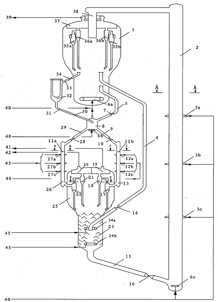
[0125] in the approximate figure 1 The test is carried out on the new fluid catalytic cracking pilot plant of the device shown. Both the heavy oil downcomer reactor and the light hydrocarbon downcomer reactor of the new fluid catalytic cracking pilot plant can be flexibly replaced according to process requirements. The heavy oil down tube reactor processes the same Daqing atmospheric residue as the comparative example, and the light hydrocarbon down tube reactor processes the catalytic gasoline produced by the heavy oil down tube reactor. The catalyst is commercially available CC-20D catalytic cracking industrial balance same catalyst.

[0126] The design capacity of the heavy oil down tube reactor is 60kg / d, simulating the full back refining operation, the heavy oil raw material is mixed with the recycle oil and enters the heavy oil down tube reactor through the feed nozzle; the designed capacity of the light hydrocarbon down tube reactor is 30 kg / d , the carbon content of ...

Embodiment 3

[0129] According to Example 2, the main difference lies in the regeneration temperature, scorch intensity and scorch time of the turbulent bed regenerator and the riser regenerator, the average gas linear velocity of the riser regenerator, the temperature of the mixed regeneration catalyst, and the reaction of the heavy oil downcomer The fuel oil ratio of the reactor and the light hydrocarbon downcomer reactor, and the recycle ratio of the heavy oil downcomer reactor. See Table 6 for the main operating conditions and product distribution of the new FCC unit implemented in this implementation. The main properties of the liquid products of the new fluid catalytic cracking unit are shown in Table 7.


PUM

PropertyMeasurementUnit
lengthaaaaaaaaaa
lengthaaaaaaaaaa
lengthaaaaaaaaaa

Abstract

The invention disclosed a downlink catalytic cracking device.The device mainly includes equipment such as heavy oil downward tube reactors, light hydrocarbon downbone reactors, sinking device, improving pipe regeneration, turbulent bed recycler, catalyst mixing tank and external heat device.The turbulent bed regeneration device is connected to the hybrid tube of the high -temperature catalyst of the catalyst mixing tank and the external thermal device; the catalyst mixed tanks are connected to the subsidencer through the heavy oil down tube reactor and the light hydrocarbon down tube reactor;The device is connected to the improvement of the pipe regeneration;The present invention can improve the distribution of catalytic cracking products, increase light oil receipts, and reduce the production rate of qi and coke; it can also produce low olefin content catalyzed gasoline and high sixteenane value catalytic diesel;Lost.

Description

technical field [0001] The invention relates to the field of catalytic cracking of hydrocarbon oil in the absence of hydrogen, in particular to a downward catalytic cracking device. Background technique [0002] At present, although the devices used in the catalytic cracking process in the petrochemical industry are various, the process form of the reaction regeneration system is basically the same. Most of them use a single riser reactor (or a combination of a single riser and a fast stage reactor) and a turbulent bed regenerator (or a two-stage regenerator combining a turbulent bed and a fast bed). Catalyst and raw oil are contacted and mixed at the bottom of the riser and then reacted upward along the riser. The reactant flow enters the settler from the outlet at the top of the riser to separate the reaction oil gas from the catalyst; Enter the regenerator to regenerate coke; the regenerated catalyst returns to the bottom of the riser for recycling. In the above-mention...

Claims


Application Information

Patent Timeline
Patent Type & Authority Patents(China)
IPC IPC(8): C10G55/06
Inventor 陈曼桥王文柯武立宪张亚西孟凡东樊麦跃陈章淼黄延召李秋芝吴辰捷
Owner CHINA PETROCHEMICAL CORP
Why Eureka
Try Eureka