Sealing chain

A technology of annular sealing and inner chain link, applied in the field of sealing chain, can solve the problems of shortened sealing life of sealing parts, reduced sealing effect, leakage of lubricating oil, etc., and achieve the effect of improving sealing effect

Inactive Publication Date: 2008-07-02
TSUBAKIMOTO CHAIN CO
View PDF1 Cites 8 Cited by
  • Summary
  • Abstract
  • Description
  • Claims
  • Application Information

AI Technical Summary

Problems solved by technology

[0006] There is such a problem in the above-mentioned existing seal chain, that is, the extrusion force of the V-shaped ring that squeezes the inner seal ring on the inner link plate is weak, and the V-shaped ring between the inner link plate and the inner seal ring and the V-shaped ring are weak. A gap is created between the end portion of the ring and the outer link plate, and the lubricating oil sealed between the bush and the pin, which is a bearing part, leaks out of the gap
[0007] In addition, in order to prevent the end of the V-ring from sliding contact with the outer link plate and reduce the sealing effect, it is necessary to perform surface finishing to reduce the surface roughness of the outer link plate. Problems that lead to increased processing workload
[0008] Furthermore, when excessive sliding contact wear occurs between the inner surface of the outer link plate with a large surface roughness and the sleeve end surface, the movement amount of the inner link composed of the sleeve and the inner link plate in the chain width direction will increase, so there is a problem that the gap between the inner link plate and the outer link plate becomes smaller due to the inner link shifting to one side in the chain width direction during chain operation. On that side, the seal components consisting of the V-ring, O-ring, inner seal ring, and outer seal ring will be significantly worn and damaged to shorten the seal life, and the gap between the inner link plate and the outer link plate will become smaller. The large side is in an incompletely sealed state, resulting in reduced sealing performance

Method used


Image

  • Sealing chain
  • Sealing chain
  • Sealing chain

Examples


Embodiment

[0032] Next, the sealing chain 100 as an embodiment of the present invention will be described with reference to the accompanying drawings.

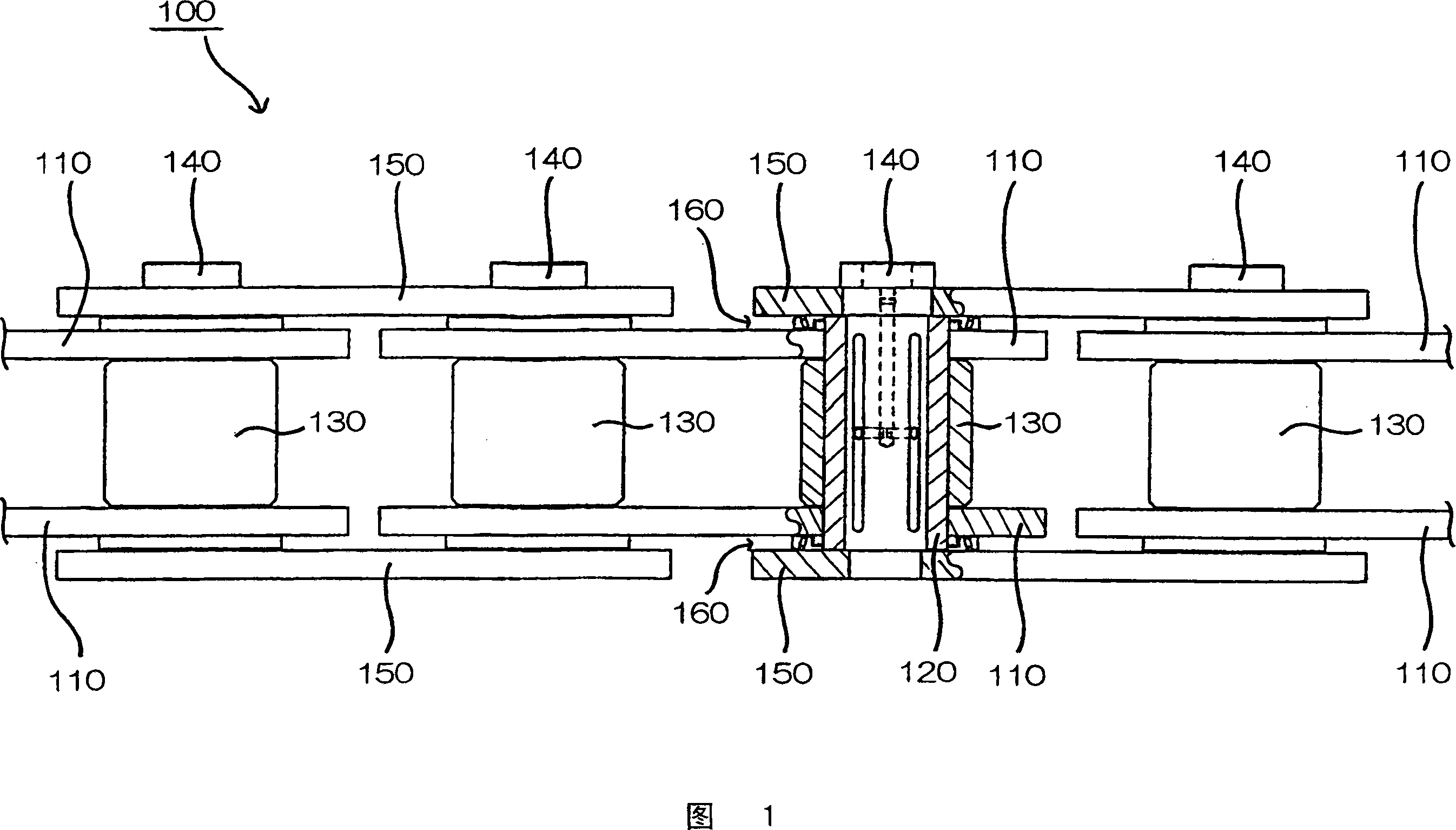
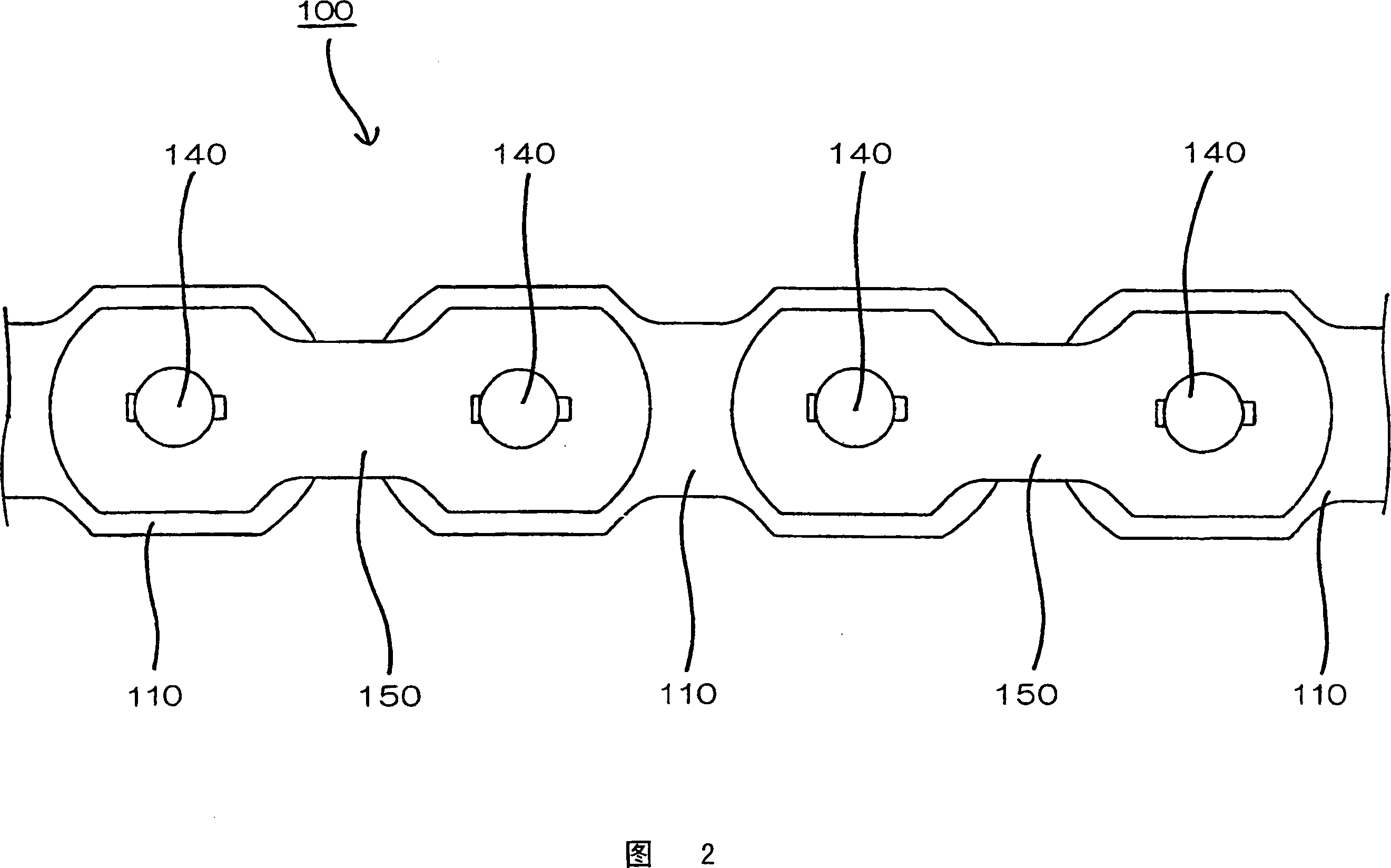
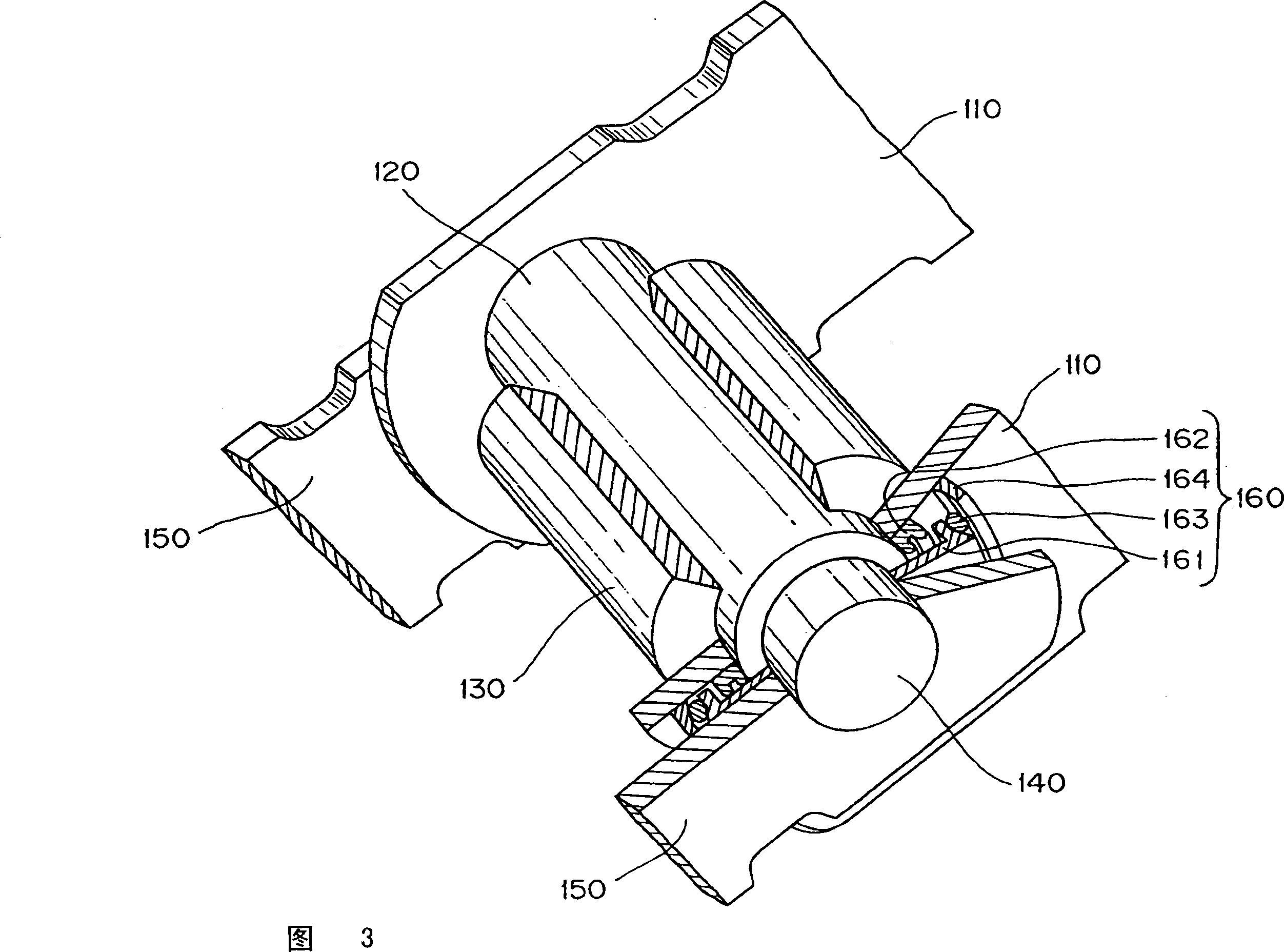
[0033] Here, FIG. 1 is an overall schematic diagram of a partial section of the sealing chain according to the first embodiment of the present invention, FIG. 2 is a partial sectioned side view of the sealing chain shown in FIG. 1 , and FIG. 4 is an explanatory view of a part of the sealing chain shown in FIG. 1, and FIG. 5 is an explanatory view of the sealing mechanism used in the sealing chain shown in FIG. 1.

[0034] First of all, the seal chain 100 of the first embodiment of the present invention is a seal chain used as a bucket chain in a continuous unloader for unloading iron ore, coal, etc., as shown in Figures 1 to 4, has: A pair of separate inner link plates 110, 110 are press-fitted into a pair of front and rear sleeves 120, 120 fitted in the sleeve press-in holes 111 of the inner link plate 110, and are rotatably fitted outs...


PUM


Abstract

The present invention provides a sealing chain, capable of preventing lubricant between a connecting pin and a sleeve from leaking as well as preventing dust from enterring, avoiding the sleeve and an outer link plate to sliding contact with each other directly, so to play excellent sealing performance for a long time and have long sealing lifetime without implementing surface thin processing to the outer link plate. The sealing mechanism (160) of the sealing chain (100) setting between the outer link plate (150) and an inner link plate (110) includes: a ring sealing piece supporting component (161), a first elastic sealing piece (162), a second elastic sealing ring (163) and a steeliness sealing ring (164).

Description

technical field [0001] The present invention relates to a sealing chain used for transportation (conveying), power transmission (transmission), etc., especially a sealing chain used as a bucket chain in a continuous unloader for unloading iron ore, coal, etc. Background technique [0002] Sealed chains are generally used in a dusty atmosphere, and a sealing mechanism is provided between the inner link plate and the outer link plate of the chain to prevent the leakage of lubricating oil sealed between the connecting pin and the sleeve and the entry of external dust. With regard to this sealing mechanism, various proposals have been made so far. [0003] In the past, the following sealing chain has been known: the inner link formed by press-fitting the two ends of the front and rear pair of sleeves into the sleeve press-fitting holes of the left and right inner link plates, and the inner link which respectively penetrates The two ends of the front and rear pair of pins in the...

Claims


Application Information

Patent Timeline
Patent Type & Authority Applications(China)
IPC IPC(8): F16G13/02B65G17/38
CPCB65G17/38B65G19/20B65G65/16F16G13/06F16J15/16
Inventor 山根健太郎藤原诚
Owner TSUBAKIMOTO CHAIN CO
Why Eureka
Try Eureka