Laser emission axis and mechanical base level coaxiality measuring method based on secondary light source

A technology of coaxiality measurement and auxiliary light source, which is applied in the field of measurement and can solve the problems of measurement, beam divergence angle, small pointing control accuracy, etc.

Inactive Publication Date: 2008-07-02
HARBIN INST OF TECH
View PDF0 Cites 18 Cited by
  • Summary
  • Abstract
  • Description
  • Claims
  • Application Information

AI Technical Summary

Problems solved by technology

[0003] In order to solve the problem that the angle between the laser emitting axis and the mechanical reference plane needs to be strictly measured in an optical test system with small beam divergence angle and high pointi

Method used


Image

  • Laser emission axis and mechanical base level coaxiality measuring method based on secondary light source
  • Laser emission axis and mechanical base level coaxiality measuring method based on secondary light source

Examples


specific Embodiment approach 1

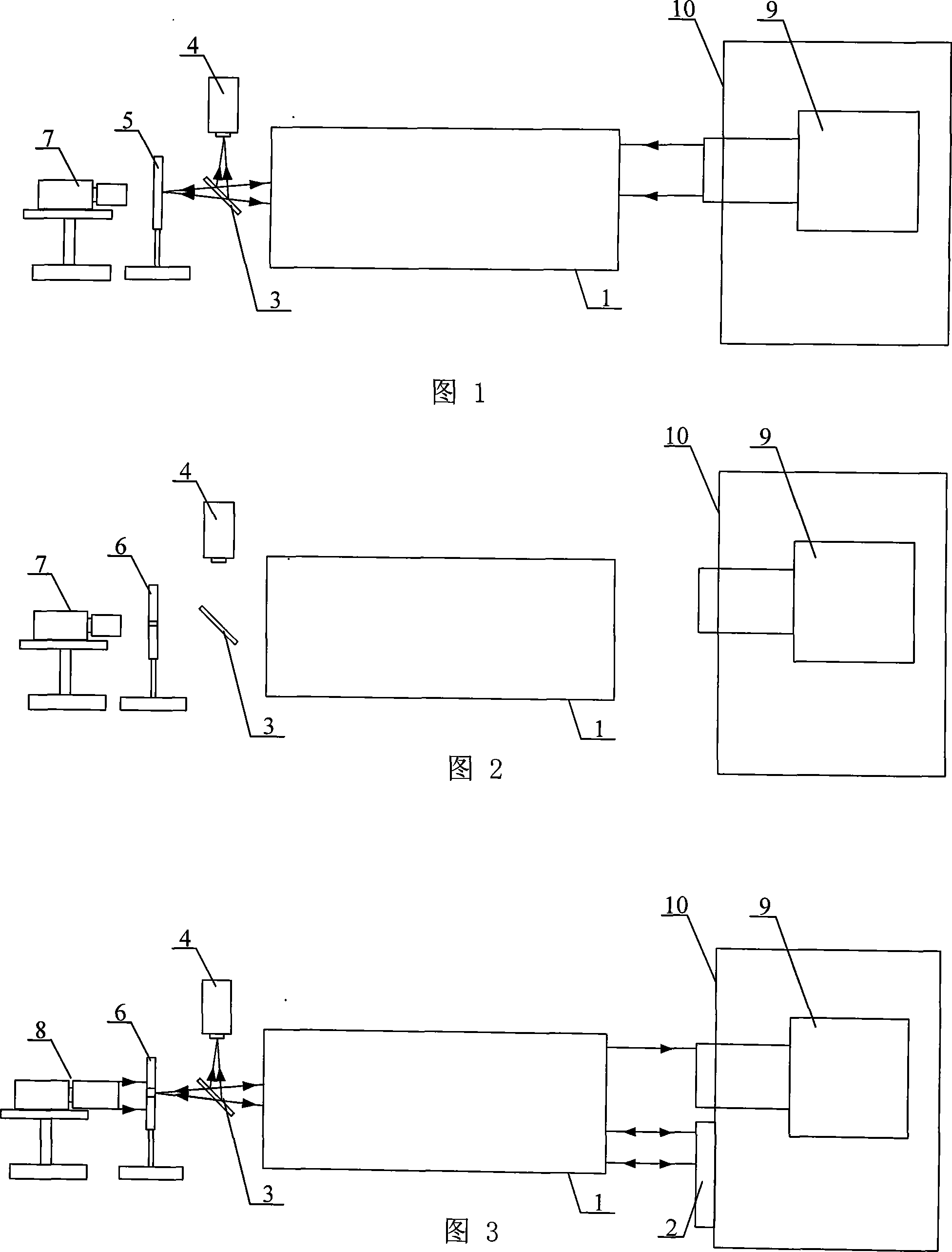
[0013] Specific implementation mode 1: This implementation mode is described in conjunction with FIGS. 1 to 5. The steps of this implementation mode are as follows:

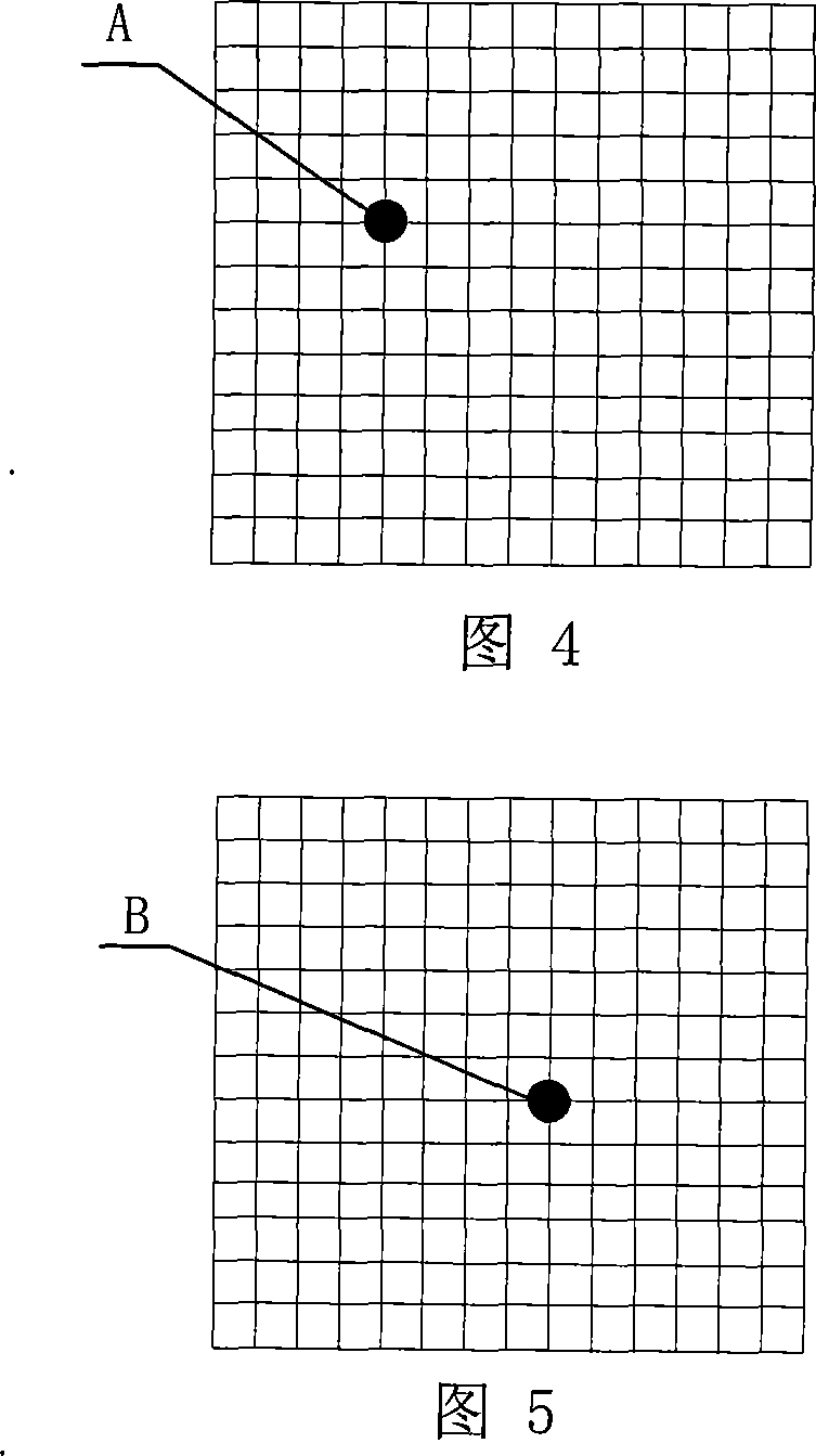
[0014] Step 1: Detect the exit spot of the laser emission system 9 under test: the laser emission system 9 under test emits a laser beam, the laser beam is focused by the telephoto collimator 1, and after focusing, the measured laser beam is irradiated on the light outlet of the telephoto collimator 1 On the 1:1 beam splitter 3 between the focal point, 50% of the measured laser beam is reflected by the beam splitter 3 and focused on the CCD detector 4, and the position of the imaging spot is recorded as A(x 1 ,y 1 ), another 50% of the measured laser beam forms a point image on the imaging screen 5, and the spot position is recorded by the microscopic CCD detector 7;

[0015] Step 2: Install the pinhole diaphragm: turn off the laser emitting system, remove the imaging screen 5, replace the shading plate 6 with t...

specific Embodiment approach 2

[0020] Specific embodiment two: the difference between this embodiment and specific embodiment one is that the center position of the small hole of the light shielding plate 6 is adjusted in the step 2, and the small hole is placed at the focal plane of the telephoto collimator 1. The CCD detector 7 monitors the position of the center of the pinhole while the position of the CCD detector 7 remains unchanged, and adjusts it at the same time so that the center of the pinhole of the shading plate 6 coincides with the position of the imaging spot of the emitted light path of the measured laser emitting system 9 . Other components and steps are the same as those in Embodiment 1.

specific Embodiment approach 3

[0021] Embodiment 3: This embodiment differs from Embodiment 1 in that the telephoto collimator 1 has a focal length of 12 m and an aperture of 400 mm. Other components and steps are the same as those in Embodiment 1.


PUM

PropertyMeasurementUnit
Caliberaaaaaaaaaa

Abstract

A method is provided to measure the coaxiality between a laser emission shaft and a mechanical reference surface based on a secondary light source. The invention relates to the measurement field and solves the problem that no method is available for accurately measuring the included angle between the laser emission shaft and the mechanical reference surface in an optical test system with small beam divergence angle and strict requirement for pointing control accuracy. The method comprises the following steps of: firstly detecting emergent light spots of a laser emission system to be measured; then installing a porous light diaphragm; installing the secondary light source for the detection of reflected light spots; and finally calculating the directional angular deviation and the pitch angle deviation. Based on the secondary light source and a beam splitting system, the invention can increase the measurement accuracy up to 0.1 Mu rad by focal plane imaging method, and also can prevent the minimal measurement range being limited by the size of light spots.

Description

technical field [0001] The invention relates to the field of measurement, in particular to a method for measuring the coaxiality of a laser emission axis and a mechanical reference plane based on an auxiliary light source. Background technique [0002] When installing the laser emission system on the mechanical support platform, it is required that the laser emission axis be precisely aligned with the normal line of the reference plane of the support platform, which requires high-precision coaxiality between the laser emission axis and the mechanical reference plane during the installation process. Measurement. At present, most optical systems do not have strict requirements on the angle difference between the optical axis and the mechanical axis, and do not need to measure the difference between precision. However, for an optical test system with a small beam divergence angle and high pointing control accuracy, the angle between the laser emission axis and the mechanical r...

Claims


Application Information

Patent Timeline
IPC IPC(8): G01B11/26
Inventor 谭立英马晶韩琦琦刘剑峰于思源杨玉强俞建杰
Owner HARBIN INST OF TECH
Why Eureka
Try Eureka