Control circuit and method for multi-mode switching boost/down rectifier

A control circuit and switchable technology, which is applied in the direction of conversion equipment without intermediate conversion to AC, can solve the problems of complex circuits, difficult control of manufacturing process, and inability to quickly fine-tune, etc., and achieve the effect of simple logic rules and simple design methods

Inactive Publication Date: 2008-07-02
FARADAY TECH CORP
View PDF2 Cites 26 Cited by
  • Summary
  • Abstract
  • Description
  • Claims
  • Application Information

AI Technical Summary

Problems solved by technology

The disadvantage is that the circuit becomes complicated, because many reference voltages need to be generated, and the process is not easy to control
Another shortcoming is that the switching time of the switch is determined according to the comparison between the triangle wave control signal 409 and the precise reference voltage signal 407, so the duty cycle of the switch is fixed, instead of using the control signal V of the comparator 403 CL It determines the time point of switch switching, so it cannot be quickly fine-tuned according to the weight of the load 214. There are only several fixed operation modes, so it is not sensitive enough

Method used


Image

  • Control circuit and method for multi-mode switching boost/down rectifier
  • Control circuit and method for multi-mode switching boost/down rectifier
  • Control circuit and method for multi-mode switching boost/down rectifier

Examples


Embodiment Construction

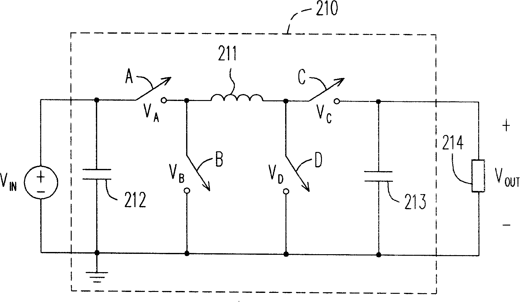
[0067] Figure 5 A multi-mode switching buck-boost rectifier 510 and its control circuit 520 are shown according to an embodiment of the present invention. The multi-mode switching buck-boost rectifier 510 includes switches A, B, C, and D, an inductor 515 , and an output capacitor 516 . Switch A receives the input voltage V IN , switch B is coupled between switch A and ground, inductor 515 is coupled between switch A and switch B, switch D is coupled between inductor 515 and ground, switch C is coupled between inductor 515 and switch d. The output capacitor 516 is coupled between the switch C and the ground, and the output capacitor 516 provides the output voltage V of the multi-mode switching buck-boost rectifier 510 OUT to load 517.

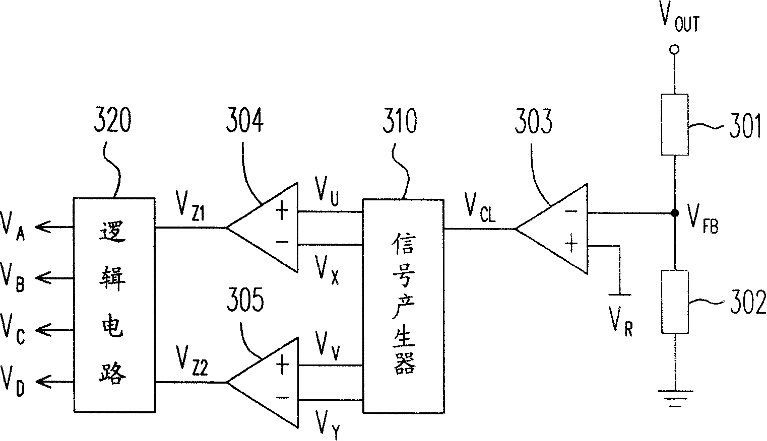
[0068] The control circuit 520 includes a comparator 521 , a triangular wave generator 540 , a logic circuit 550 , and a voltage dividing circuit 530 . Wherein the comparator 521 according to a feedback voltage V FB with a reference volta...


PUM


Abstract

The invention relates to a control circuit and a control method of a switching buck-boost rectifier with a plurality of modes. Two triangle waves for controlling are used for matching the control circuit with variable load, and a guide circuit for each switch and timing relationship of stop control are designed. At most two switches act within each work period of each mode. The circuit is easy in design and only requires simple digital components such as a comparator and a logic valve rather than a complex analogy circuit.

Description

technical field [0001] The present invention relates to a multi-mode switching buck-boost rectifier, and in particular to a control circuit and method for a multi-mode switching buck-boost rectifier. Background technique [0002] Please refer to figure 1 , figure 1 Shown is a traditional multi-mode switching buck-boost rectifier and its control circuit structure diagram. Multi-mode switching means that there are three operations including boost mode, buck mode, and buck-boost mode. As the name implies, boost mode means that in a certain duty cycle, its input voltage V IN Boost to get another voltage output. The step-down mode represents that in a certain working cycle, the input voltage V IN Step down to get another voltage output. The buck-boost mode represents that in a certain working cycle, the input voltage V IN Boost first and then step down, or first step down and then step up to get another voltage output. Input voltage V IN Input the multi-mode switching bu...

Claims


Application Information

Patent Timeline
IPC IPC(8): H02M3/07
Inventor 陈科宏林永欣游正达
Owner FARADAY TECH CORP
Why Eureka
Try Eureka