Triangle wave generating circuit and PWM modulation circuit

A technology for generating circuits and triangular waves, applied in the direction of pulse duration/width modulation, pulse generation, electrical components, etc., can solve the problems of generating bias, increasing the number of components, etc., and achieve the effect of low output impedance

Inactive Publication Date: 2008-07-02
PANASONIC CORP
View PDF1 Cites 22 Cited by
  • Summary
  • Abstract
  • Description
  • Claims
  • Application Information

AI Technical Summary

Problems solved by technology

In the previous example 2, by inserting a high-speed buffer in the subsequent stage of the output, although the blunt phenomenon of the waveform was avoided, the number of components increased, and an offset was generated between the two outputs due to the component error of the buffer. new question

Method used


Image

  • Triangle wave generating circuit and PWM modulation circuit
  • Triangle wave generating circuit and PWM modulation circuit
  • Triangle wave generating circuit and PWM modulation circuit

Examples


Embodiment Construction

[0025] Hereinafter, the present invention will be described based on FIGS. 1 to 5 showing embodiments.

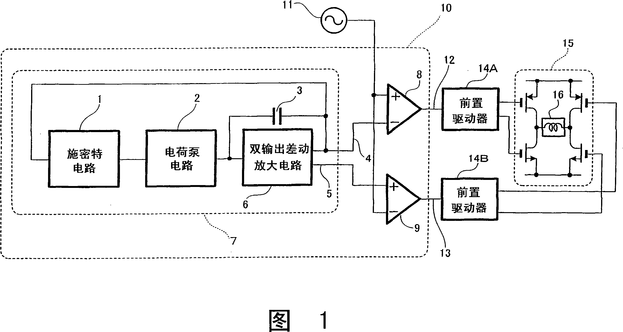
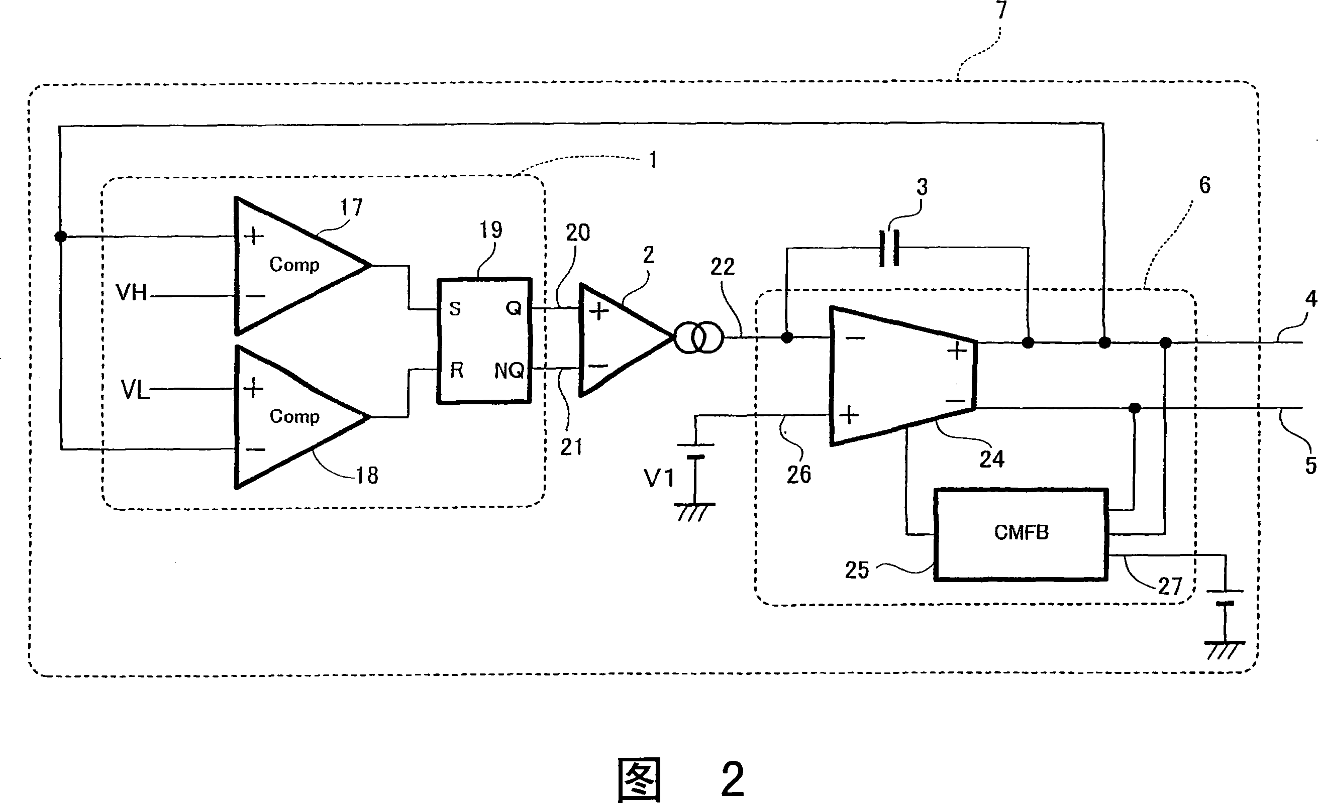
[0026] FIG. 1 is a block diagram of an actuator drive device using a PWM modulation circuit which is an embodiment of the present invention, and FIG. 2 shows a triangular wave generating circuit in FIG. 1 .

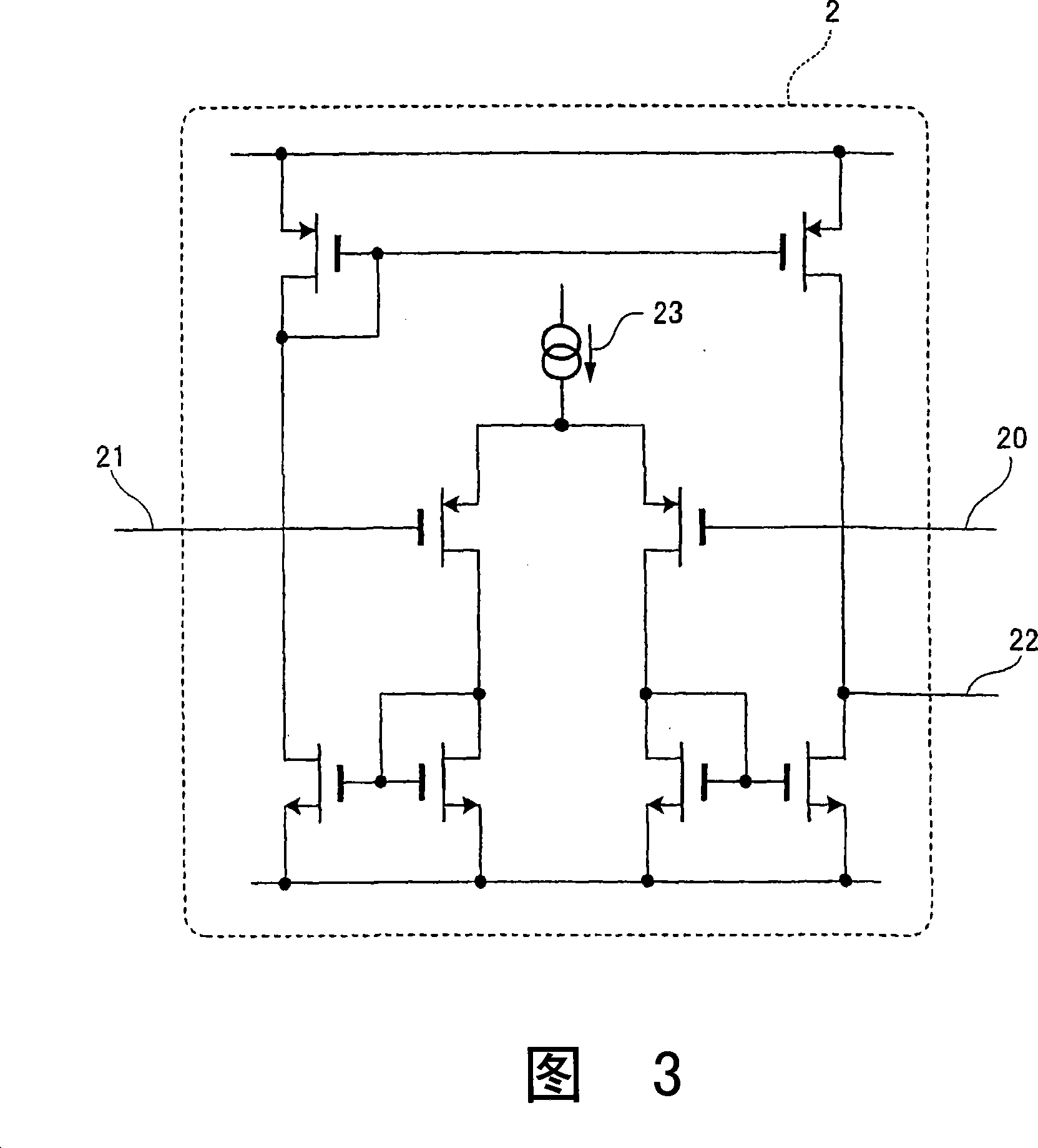
[0027] In FIG. 1 , the triangular wave generating circuit 7 has a Schmitt circuit 1 that has two threshold voltages with different values ​​for one input, and when the input voltage rises and reaches the first threshold, the output takes the first threshold. 1 output state, if the voltage value of the input drops and reaches the 2nd threshold value, the output takes the 2nd output state; the charge pump circuit 2, the charge pump circuit 2 connects the output of the Schmidt circuit 1 to its input, and has an output current It is a certain value of current, and its direction is switched to pull in and output in two directions; a capacitor 3, one end of the capacitor 3 i...


PUM


Abstract

The present invention relates to an oscillator outputting two triangle waves having the same amplitude and whose phases are inverted; and a pulse width modulator using the oscillator. A capacitor 3 is charged or discharged by a charge pump circuit 2 controlled by a Schmitt circuit 1 , and a voltage integrated by a two-output differential amplification circuit 6 is positively fed back to the input of the Schmitt circuit 1 to output two triangle waves having the same amplitude and whose phases are inverted. Since the output stage is composed of a differential amplification circuit, the circuit has low output impedance and is protected from wiring capacity and connected input capacity, and since integral operation is caused to be performed by the differential amplification circuit, the distortion in the waveform of the triangle waves can be prevented.

Description

technical field [0001] The invention relates to an oscillating circuit which outputs two triangular waves with the same amplitude and opposite phases and a PWM modulation circuit using the oscillating circuit. Background technique [0002] In the past, when generating two triangular waves with the same amplitude and opposite phases, the triangular wave generated by one triangular wave generator was inverted by an amplifier. Conventional Example 1 and Conventional Example 2 are shown in FIGS. 6 and 7 . [0003] In the conventional example 1 shown in FIG. 6, the triangular wave generated by the triangular wave oscillator 100 and the output voltage of the differential amplifier circuit 101 are resistively divided by equal-value resistors R1 and R2. The midpoint voltage of the differential amplifier circuit is fed back to the inverting input terminal (-) of the differential amplifier circuit 101, so that the set reference voltage is given to the non-inverting input terminal (+)...

Claims


Application Information

Patent Timeline
Patent Type & Authority Applications(China)
IPC IPC(8): H03K4/06H02M1/08H02M7/5387H02M3/07H02M7/00
CPCH03K4/066H03K7/08
Inventor 久米智宏
Owner PANASONIC CORP
Why Eureka
Try Eureka