Ultrasonic diagnostic equipment

A diagnostic device, ultrasonic technology, applied in the direction of acoustic wave diagnosis, infrasonic wave diagnosis, ultrasonic/sonic wave/infrasonic wave diagnosis, etc., can solve the problem of unrecognizable target, invisible, uncertain blood flow, etc. question

Active Publication Date: 2008-07-09
OLYMPUS CORP
View PDF1 Cites 9 Cited by
  • Summary
  • Abstract
  • Description
  • Claims
  • Application Information

AI Technical Summary

Problems solved by technology

[0005] Therefore, when a tumor image is displayed in the B-mode image display area on the display surface of the image display, if the blood flow display area is to be moved to a part where the tumor image exists to display the blood flow of that part, if When the blood flow display area overlaps with the tumor image during the movement, the tumor image is covered and cannot be seen, and the target cannot be confirmed
[0006] Usually, the ultrasonic transceiver (transmitter) such as an ultrasonic probe is touched by the operator to the subject, so the direction is easy to change
Therefore, it is necessary to correct the direction deviation of the transceiver while viewing the screen so that the tumor image always appears on the display screen. However, if the target is invisible in the middle as described above, even if the direction of the transceiver deviates, it cannot be corrected.
As a result, it is uncertain whether the blood flow displayed in the blood flow display area must be the blood flow of the desired part

Method used


Image

  • Ultrasonic diagnostic equipment
  • Ultrasonic diagnostic equipment
  • Ultrasonic diagnostic equipment

Examples


Embodiment 1

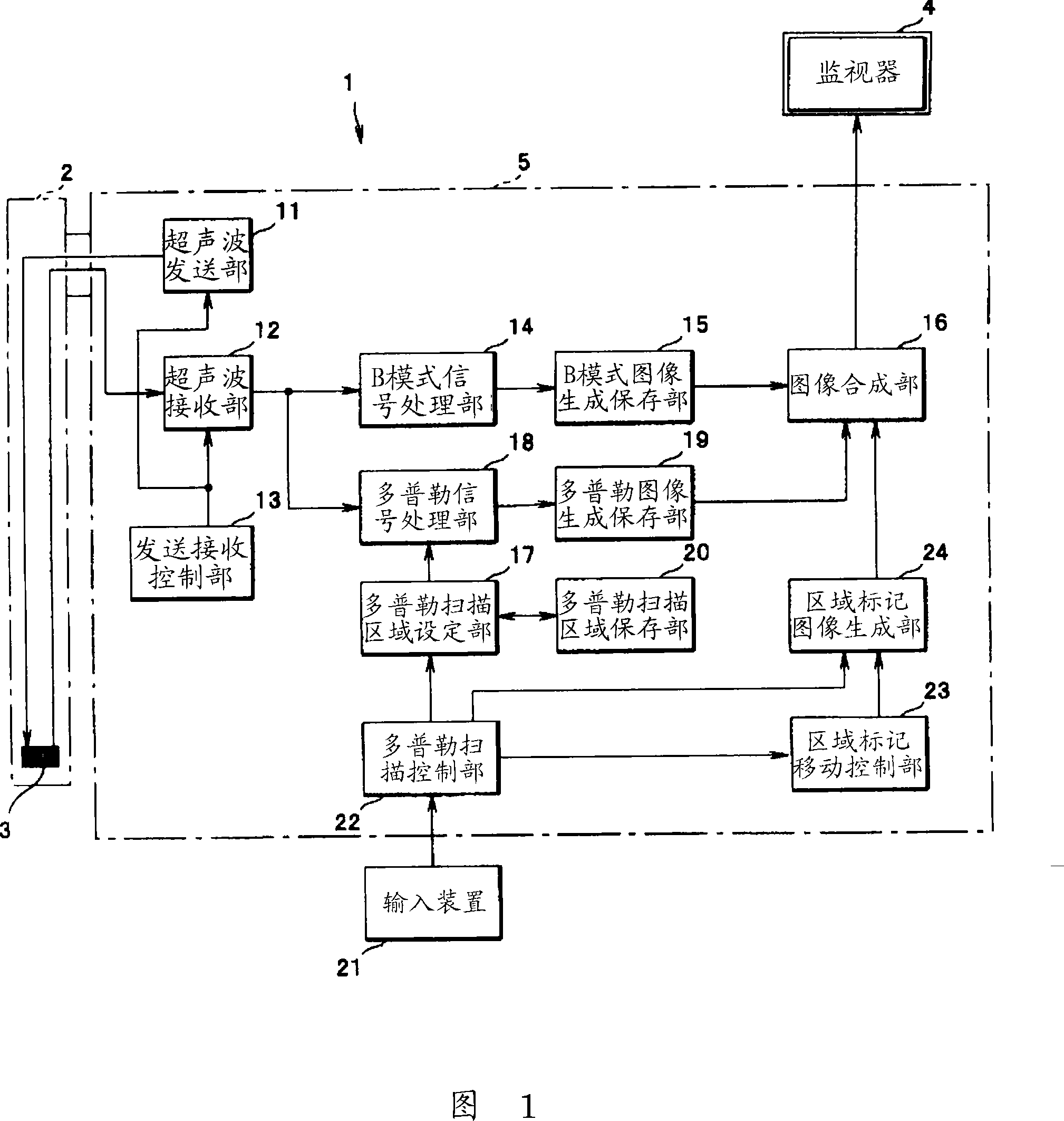
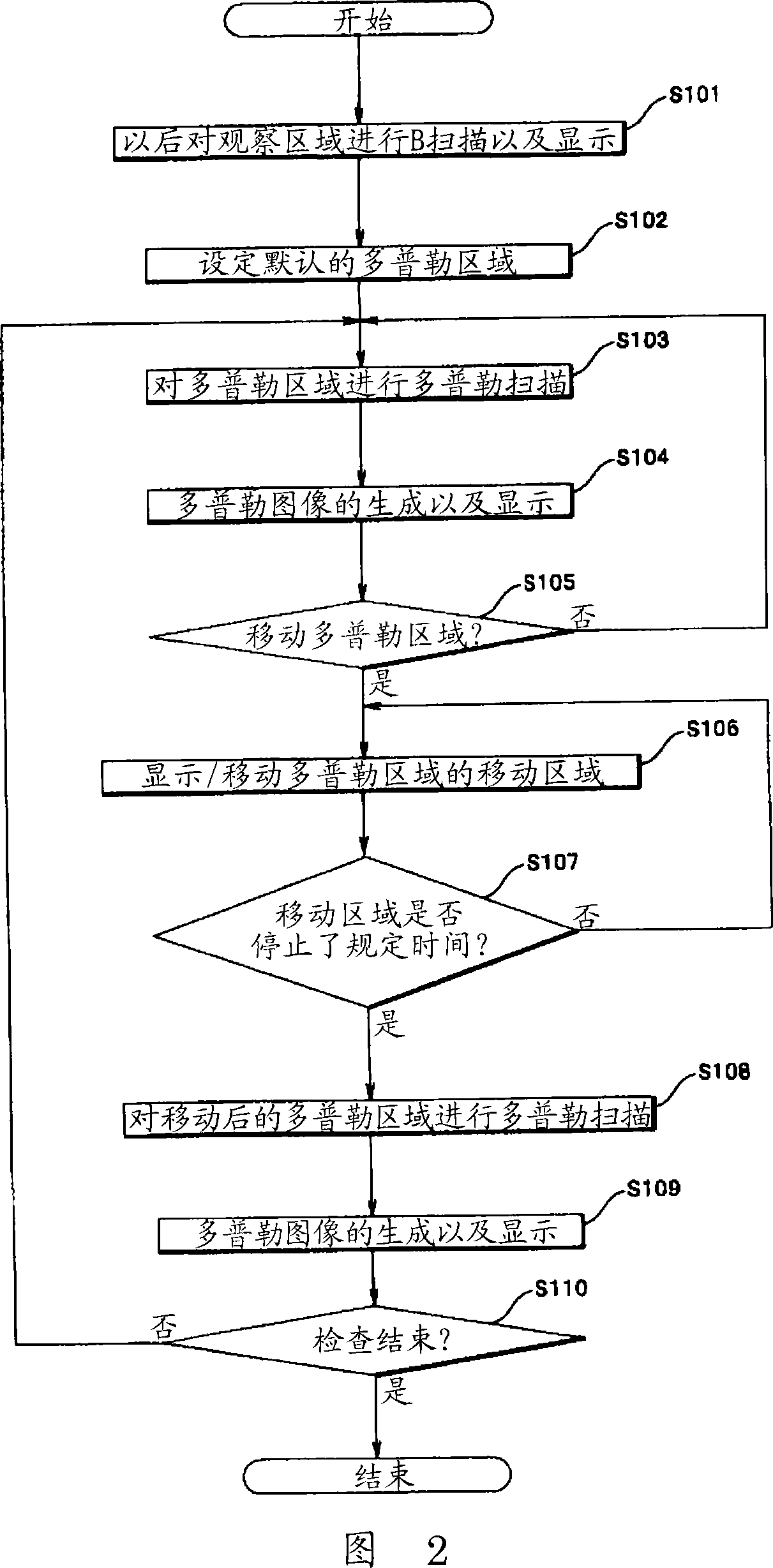
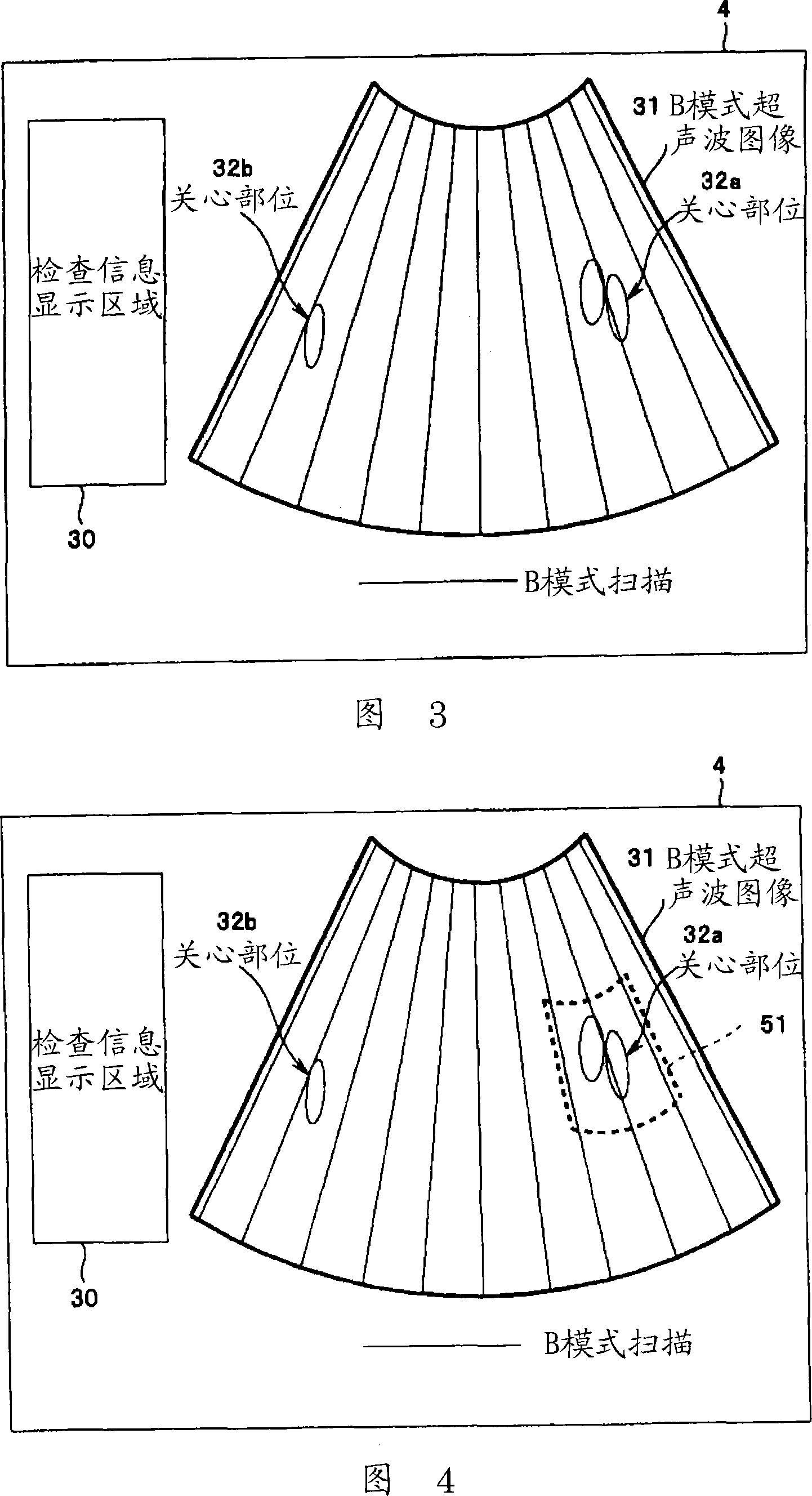
[0073] 1 to FIG. 7 relate to Embodiment 1 of the present invention. FIG. 1 is a structural diagram showing the structure of an ultrasonic diagnostic apparatus, FIG. 2 is a flow chart showing a processing flow of the ultrasonic diagnostic apparatus of FIG. 1 , and FIG. Fig. 4 is a second diagram illustrating the processing of Fig. 2, Fig. 5 is a third diagram illustrating the processing of Fig. 2, Fig. 6 is a fourth diagram illustrating the processing of Fig. 2, Fig. 7 is a fifth diagram illustrating the processing of FIG. 2 .

[0074] As shown in FIG. 1 , the ultrasonic diagnostic apparatus 1 of the present embodiment is provided with: an ultrasonic probe 2 which is inserted into a luminal organ in a body cavity, and has a care function at the distal end thereof for monitoring the affected part in the luminal organ, etc. an ultrasonic vibrator unit 3 for transmitting and receiving ultrasonic waves; and an image processing device 5 that ultrasonically drives the ultrasonic vibr...

Embodiment 2

[0106] 8 to 34 relate to Embodiment 2 of the present invention, FIG. 8 is a flow chart showing the processing flow of the ultrasonic diagnostic apparatus, FIG. 9 is the first diagram for explaining the processing of FIG. 8 , and FIG. The second figure, Fig. 11 is the third figure illustrating the processing of Fig. 8, Fig. 12 is the fourth figure illustrating the process of Fig. 8, Fig. 13 is the fifth figure illustrating the process of Fig. 8, and Fig. 14 is The sixth figure illustrating the processing of FIG. 8, FIG. 15 is the seventh figure illustrating the processing of FIG. 8, and FIG. 16 is the eighth figure illustrating the processing of FIG. 8. FIG. Figure 18 is the first figure for explaining the process of Figure 17, Figure 19 is the second figure for explaining the process of Figure 17, Figure 20 is the figure for explaining the process of Figure 17 The third figure of the processing, Fig. 21 is the fourth figure illustrating the process of Fig. 17, Fig. 22 is the f...

Embodiment 3

[0134]Next, an ultrasonic diagnostic apparatus 100 according to a third embodiment of the present invention will be described in comparison with a conventional ultrasonic diagnostic apparatus. 40 and 41 are diagrams illustrating a monitor screen in a conventional ultrasonic diagnostic apparatus. In the conventional ultrasonic diagnostic apparatus, as shown in FIG. 35 , a blood flow display area (hereinafter referred to as color display area) 51a capable of color image display (hereinafter referred to as color display) of the two-dimensional distribution of blood flow is displayed in the B mode. There is only one place in the image display area 31 . Therefore, in order to simultaneously color-display a plurality of interest object parts 32a, 32b, and 32c in the B-mode image display area 31 in real time, there is only the following method: as shown in FIG. As shown in FIG. 41 , the color display area 51a designates the color display area 51b including all the plurality of targe...


PUM


Abstract

By the configuration, an observation target of which blood state needs to be grasped can be always optimally observed in real time in a Doppler image by a Color Doppler mode or a Power Doppler mode.In the present invention, an image processing device is configured by including an ultrasonic wave transmitting section, an ultrasonic wave receiving section, a transmission and reception control section, a B mode signal processing section, a B mode image generating and storing section, an image synthesizing section, a Doppler signal processing section, a Doppler image generating and storing section, a Doppler scan region setting section, a Doppler scan region storing section, a Doppler scan control section, a region marker movement control section and a region marker image generating section.

Description

technical field [0001] The present invention relates to an ultrasonic diagnostic apparatus for displaying a blood flow image in a part of a B-mode image display area in a color Doppler mode or a power Doppler mode using ultrasonic waves. Background technique [0002] In recent years, in medical ultrasonic diagnostic apparatuses, a living body is irradiated with ultrasonic waves, and the energy (power) of Doppler (Doppler) signals is used to display the two-dimensional distribution of blood flow in a color image. The method of using the energy of the Doppler signal to display the blood flow is different from the method of using the frequency of the Doppler signal to display the blood flow. Although the direction, velocity or velocity dispersion of the blood flow cannot be displayed, but in view of the high sensitivity and The unique function of displaying the position and intensity of blood flow with a high S / N ratio has become one of the useful blood flow display methods. ...

Claims


Application Information

Patent Timeline
Patent Type & Authority Applications(China)
IPC IPC(8): A61B8/06A61B8/14
CPCA61B8/00A61B8/06
Inventor 香西繁范
Owner OLYMPUS CORP
Why Eureka
Try Eureka