Knee joint endoprosthesis

A technology for knee joints and prostheses, applied in the directions of knee joints, elbow joints, joint implants, etc., can solve the problems of affecting the movement stability of knee joint prostheses and shortening the life of tibial pads, so as to ensure movement stability. sex, improve overall life expectancy

Inactive Publication Date: 2008-07-09
SICHUAN UNIV
View PDF3 Cites 40 Cited by
  • Summary
  • Abstract
  • Description
  • Claims
  • Application Information

AI Technical Summary

Problems solved by technology

However, the tibial intercondylar ridge and the tibial liner in these patents are integrated. When the wear of the tibial intercon

Method used


Image

  • Knee joint endoprosthesis
  • Knee joint endoprosthesis

Examples


Embodiment Construction

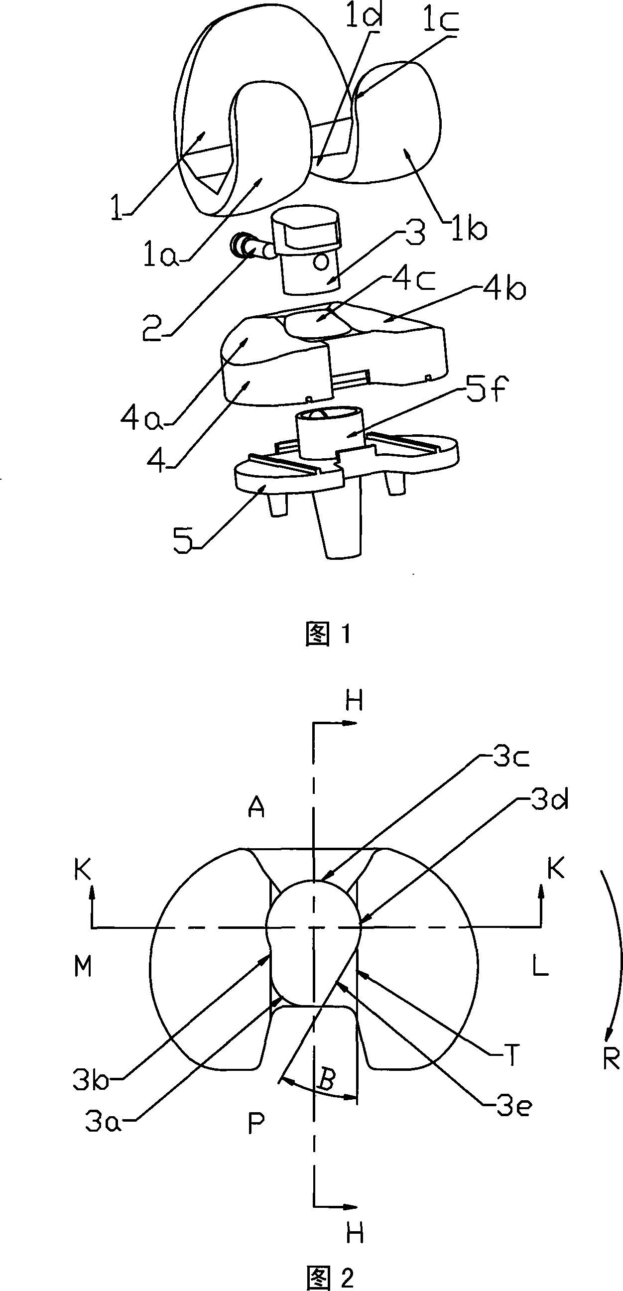
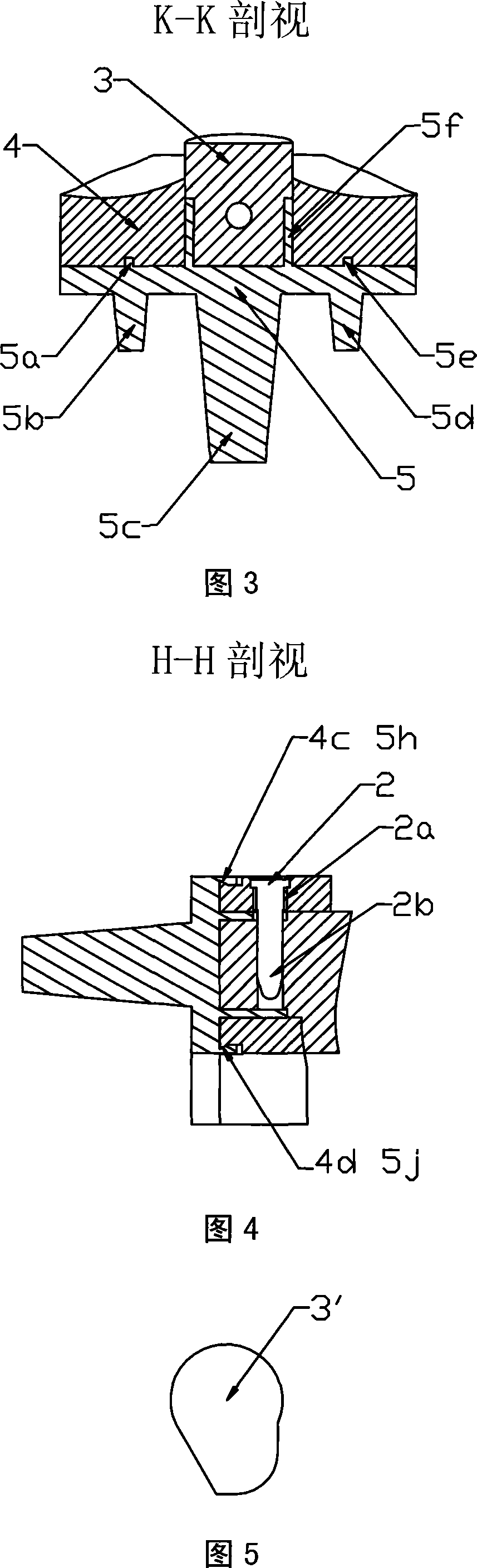
[0024] In Fig. 1, Fig. 2, Fig. 3 and Fig. 4, the femoral prosthesis 1 is made of cobalt-chromium-molybdenum alloy material, connected with the distal end of the femur through femoral mounting stems or screws, and has inner condyle 1a and outer condyle 1b . The tibial bearing 5 is made of cobalt-chromium-molybdenum alloy material, and is connected with the proximal end of the tibia through the tibial mounting stem 5c and the fixing columns 5b, 5d, wherein the tibial mounting stem 5c is pressed into the tibial medullary cavity to play a major role of fixation, fixing Columns 5b and 5d are pressed into the cut surface of the proximal tibia to prevent rotation and assist fixation. The tibial liner 4 is made of ultra-high molecular weight polyethylene material, is located between the femoral prosthesis 1 and the tibial bearing 5, has the inner bone condyle 4a and the outer bone condyle 4b, and passes along the tibial bearing A-P direction (anterior-posterior direction) The protrus...


PUM


Abstract

The present invention provides an internal knee joint prosthesis which comprises a femoral prosthesis (1) which is connected with the far end of the femoral, a tibial gasket (4) which is fixed at a tibial support (5), the tibial support which is connected with the close end of a tibia, a tibial intercondylar eminence (3) filled into the intercondylar hole (4c) of the tibial gasket (4) and the protrudent platform (5f) hole of the tibial support (5) and a bolt (2) which ensures the opposite position of the tibial intercondylar eminence (3) with the tibial gasket (4) and the tibial support (5). The inner condylar (4a) and outer condylar (4b) joint faces of the tibial gasket (4) are respectively opposite to the inner condylar (1a) and outer condylar (1b) joint faces of the femoral prosthesis (1), so as to ensure that the femoral prosthesis (1) can realize the actions of extending, bending and backwards rolling at the tibial gasket (4). The tibial intercondylar eminence (3) is extended into the condylar interval area (1d) of the femoral prosthesis, so as to ensure the knee extension stability of the knee joint. The part of the tibial intercondylar eminence (3) near the outer condyle (1b) of the femoral prosthesis (1) is excised to ensure that the femoral prosthesis (1) has larger outwards rotation angle at the bending knee position, so as to realize the deep bend of the knee joint.

Description

technical field [0001] The present invention relates to a medical artificial joint, in particular to a knee prosthesis applied to the human body, which is used to replace the human body's natural knee joint that has lost all or part of its function due to pathological changes or injuries during knee joint shaping. . Background technique [0002] The development of artificial knee joints has a history of more than 40 years. When the natural knee joint of the human body loses all or part of its function due to disease or injury, it needs to be replaced with an artificial knee joint to reconstruct the knee joint and reduce the patient's pain. illness. [0003] The so-called internal prosthesis of the knee joint includes two parts: the femoral prosthesis and the tibial prosthesis. Among them, the femoral prosthesis is connected to the distal end of the femur through a femoral mounting stem or screws, and has inner and outer condyles. The tibial prosthesis is divided into two ...

Claims


Application Information

Patent Timeline
IPC IPC(8): A61F2/38
Inventor 张国亮姚进裴福兴沈彬周宗科
Owner SICHUAN UNIV
Why Eureka
Try Eureka