Blade component for shredder
A paper shredder and blade technology, applied in the direction of knives, grain processing, household appliances, etc., can solve the problems of high cost, high torque, high power of the whole machine, etc.
- Summary
- Abstract
- Description
- Claims
- Application Information
AI Technical Summary
Problems solved by technology
Method used
Image

Examples
Embodiment approach 1
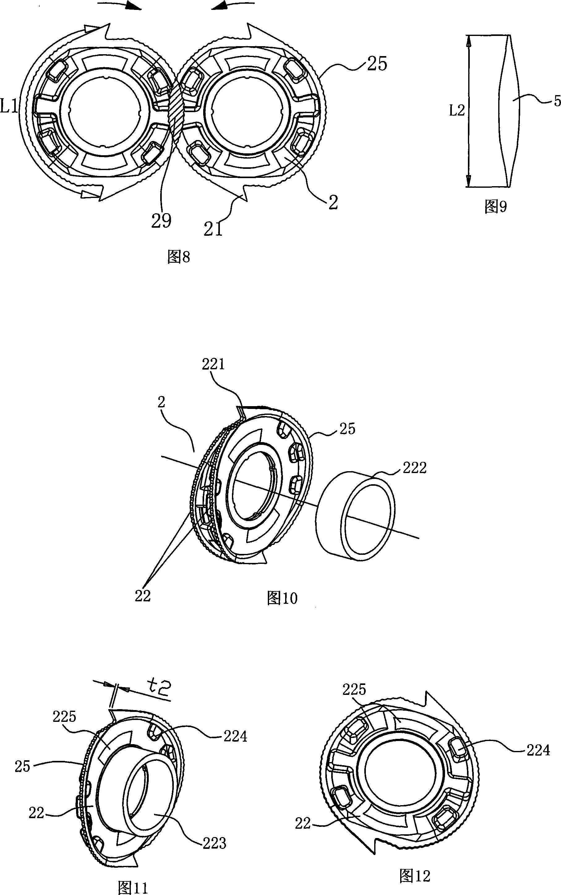
[0043]As shown in Figure 10, in this production method, each shredding blade 2 in the blade assembly is formed by a pair of metal stamping blade monomers 22 facing each other, and the sharp surface formed by stamping each blade monomer is on the outside of the blade, The same is true at the knife point 221, so as to be beneficial to utilize this noodle to cut, puncture, and cut off the paper. During installation, the blade 2 formed by the stacked blade units 22 can be sleeved on the cutter shaft through the spacer 222 so as to form a stable distance between the blades. Or as shown in Figure 11, the flange 223 stamped and formed by the blade unit 22 itself forms a uniform interval between the two blades, and the knife tips are distributed and repeated on the entire knife shaft in a staggered manner, so that the entire shredding knife set is formed. . Another advantage of this design method is that we can use thinner metal sheets to make them firm and fit inside by stamping bos...
Embodiment approach 2
[0045] See Fig. 13, the blade 2 of the present embodiment is made of a metal blank slightly larger than itself, through turning, milling, grinding and other processing techniques to make the blade turn sharp and the integral blade 23 with a sharp tip. This integral blade 23 Also can make boss 231 on its two sides or one side, as shown in Figure 14, just can form the required interval between the blades on the opposite cutter assembly of the above-mentioned embodiment without interval.
Embodiment approach 3
[0047] See Fig. 14, in this embodiment, the blade 2 and the cutter shaft 3 are designed as an integral blade assembly 30, and the blade assembly 30 consists of a round rod slightly larger than the outer diameter of the blade 2, which is integrated through multiple processes such as turning and milling. processed out. Of course, the sharp sides of the blade 2, the sharp tip and the edge of the tip are also processed together. In the blade assembly 30 processed in this way, the distance between the blades 2 has been processed and set, so this method does not need a spacer.
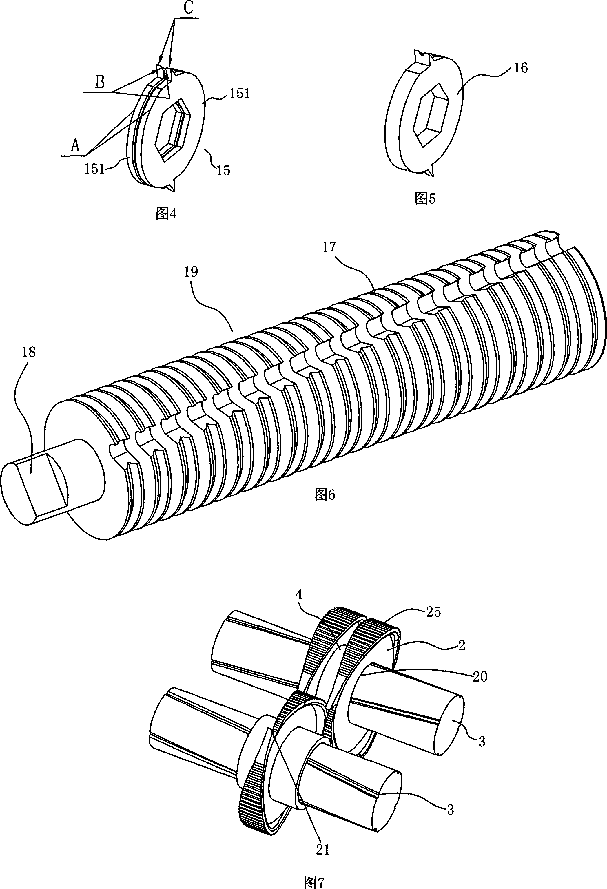
[0048] The present invention is based on the paper shredding principle of a paper shredder, and the outer contour of the blade 2 can not only be circular, but also can be made into an ellipse, a quasi-circle, or a sealed ring. In addition, in order to better shred the shredded paper with the rotation of the two blade components, the periphery of the blade can be made into small teeth as shown in Figures 7, ...
PUM
 Abstract
Description
Claims
Application Information
 - R&D
- Intellectual Property
- Life Sciences
- Materials
- Tech Scout
- Unparalleled Data Quality
- Higher Quality Content
- 60% Fewer Hallucinations
Browse by: Latest US Patents, China's latest patents, Technical Efficacy Thesaurus, Application Domain, Technology Topic, Popular Technical Reports.
© 2025 PatSnap. All rights reserved.Legal|Privacy policy|Modern Slavery Act Transparency Statement|Sitemap|About US| Contact US: help@patsnap.com