
Brake of industrial vehicle

A technology of industrial vehicles and brakes, which is applied in the direction of foot-operated starting devices, etc., can solve the problems of insufficient braking efficiency, false parking, etc., and achieve the effect of simple structure, easy processing, and low workload

Active Publication Date: 2008-07-09
WUXI KIPOR POWER CO LTD
View PDF1 Cites 1 Cited by
  • Summary
  • Abstract
  • Description
  • Claims
  • Application Information

AI Technical Summary

Problems solved by technology

Because this kind of mechanism can appear formally locked on any tooth within a certain range, so, with the influence of factors such as physical strength, concentration, and even emotions, the operator's adjustment of the parking brake The operating force exerted by the mechanism will change, and the pawl may engage with any one of the multiple tooth slots on the ratchet wheel. The occurrence of reliable braking force becomes a probability event, which may cause braking when the vehicle is parked. Insufficient "false parking" safety hazard

Method used


Image

  • Brake of industrial vehicle
  • Brake of industrial vehicle
  • Brake of industrial vehicle

Examples


Embodiment Construction

[0035] The present invention will be further described below in conjunction with accompanying drawing and specific embodiment:

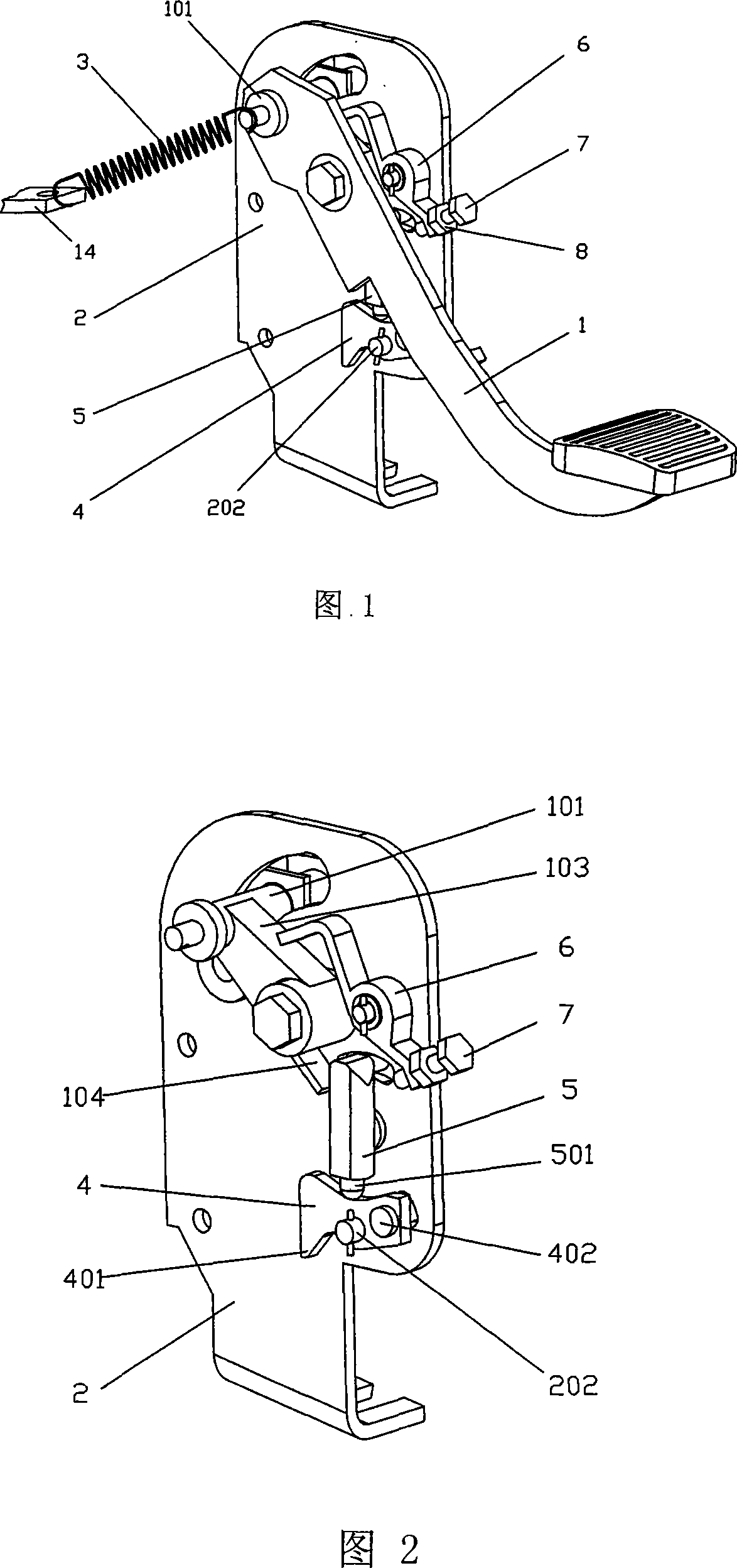
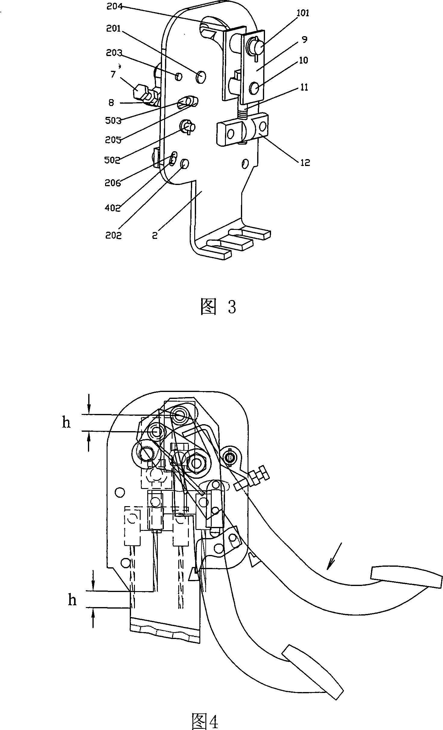
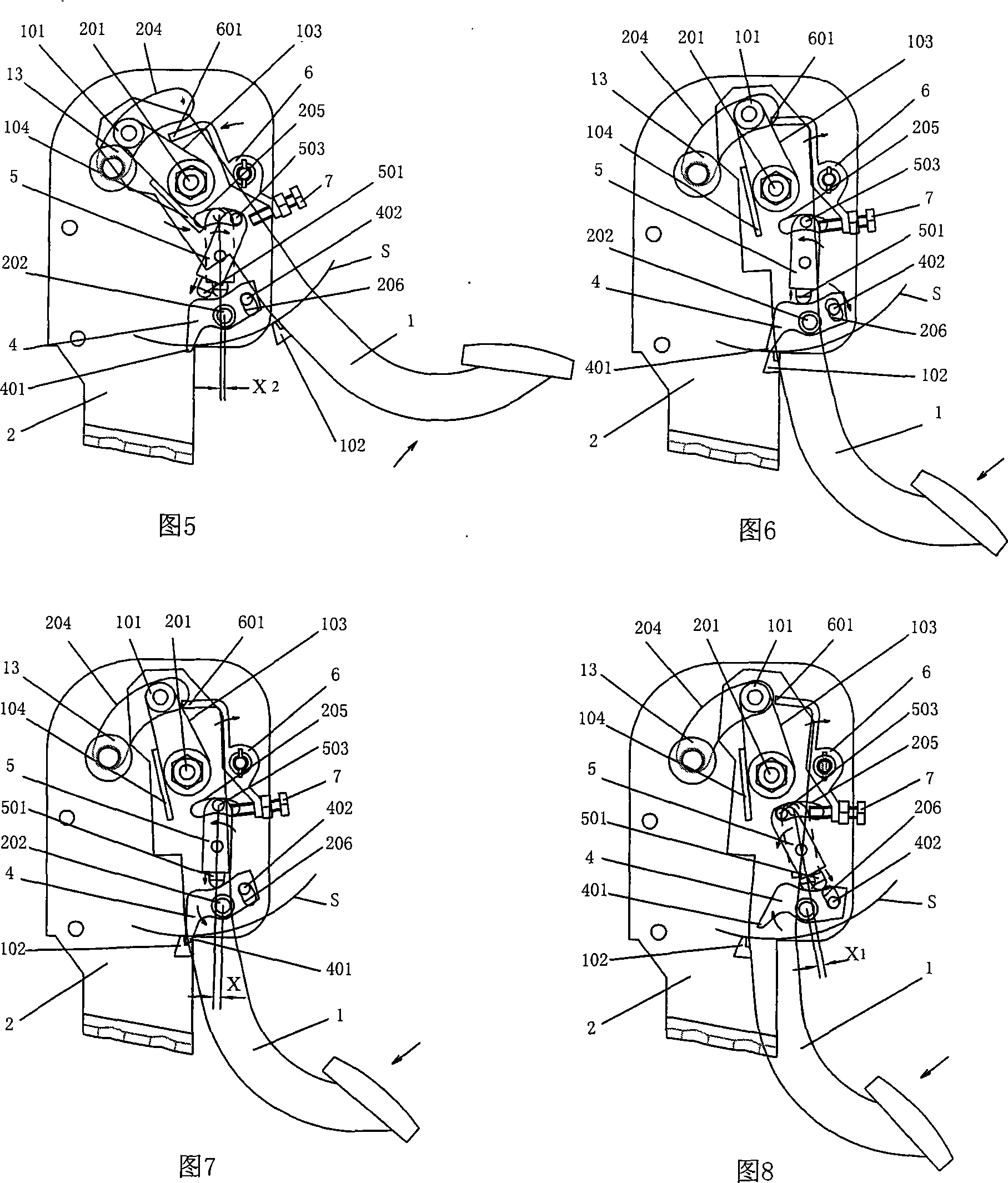
[0036] As shown in Figures 1 to 3, it includes: the pedal arm 1 and the bracket 2, the side of the pedal arm 1 opposite to the bracket 2 (the front of the bracket 2) is fixedly connected with the cable shaft 101, the pedal arm lock hook 102, and the lever thrust surface 103, the finger reset part 104, the front of the bracket 2 has the pedal arm pivot 201, the locking claw pivot 202, the control lever pivot 203, and the bracket 2 also has three arc-shaped slots through the bracket plate, respectively for the pedal Arm limiting groove 204 , finger limiting groove 205 , locking pawl limiting groove 206 .

[0037] Also includes: return spring 3, locking claw 4, locking claw tip 401, locking claw limit pin 402, elastic finger 5, finger pin 501, finger pivot 502, finger limit pin 503, control lever 6, control screw 7. Lock nut 8, cable pendant 9, hanging...


PUM


Abstract

The invention relates to a brake of industry vehicles. The brake mainly comprises a pedal arm, a support, a return spring, a lock pawl, an elastic finger, a control level, a control screw, a lock nut, zip-fastener hanging parts, a hanging scroll, an adjusting bolt, a zip-fastener balancer and an elastic body. One side of the pedal arm facing to the support is fixedly connected with a wiredrawing scroll, the latch hook of the pedal arm, the thrust face of the level, the return piece of the finger. One side of the support facing the pedal arm is fixedly connected with the pivot shaft of the pedal arm, the pivot shaft of the lock bolt pawl, and the pivot of the control level. The side is also equipped with the stop slot of the pedal arm, the stop slot of the finger and the stop slot of the lock bolt pawl. The invention has the advantages of simple structure, easy fabrication, reliable operation, being completely controlled by the pedal, the only locking position and the subsequent stable brake force due to locking at the first operating position and unlocking at the second operating position, moreover having the function of the adjustable unlocking travel and the compensation of the abrasion of the brake block.

Description

technical field [0001] The invention relates to a brake of an industrial vehicle, in particular to a parking brake control device, a mechanical brake operated by a foot pedal, and belongs to the technical field of vehicle brake control systems or components thereof. Background technique: [0002] The mechanical parking brake of the vehicle mostly relies on the locking action of the ratchet-pawl mechanism to keep the brake at the braking position, so as to ensure the reliable parking of the vehicle. [0003] Japanese Patent Publication No. JP3031045 discloses a pedal parking brake mechanism. The parking brake action is realized by the operator depressing the brake pedal and relying on the ratchet pawl to snap into the ratchet tooth groove at the corresponding position. locking. But to release the braking action, you need to manipulate a handle by hand. When the handle of releasing the brake is pulled, the pawl will come out of the tooth groove of the ratchet, so the locking ...

Claims


Application Information

Patent Timeline
Patent Type & Authority Applications(China)
IPC IPC(8): B60T7/06
Inventor 肖亨琳
Owner WUXI KIPOR POWER CO LTD
Learn More