Centrifugal flow guiding intelligent speed governing hydraulic coupler body structure

A technology of hydraulic coupling and intelligent speed regulation, which is applied to fluid transmission devices, belts/chains/gears, mechanical equipment, etc., which can solve the problems of insufficient utilization of working oil energy, reduced adaptability of couplings to loads, and problems of couplings. Unstable work and other problems, achieve significant economic and social benefits, save raw materials, reduce wall thickness and size

Inactive Publication Date: 2008-07-09
SHANGHAI JIAO TONG UNIV
View PDF1 Cites 8 Cited by
  • Summary
  • Abstract
  • Description
  • Claims
  • Application Information

AI Technical Summary

Problems solved by technology

The labyrinth oil seal of the coupler body structure is arranged along the axial direction of the coupler, and the centrifugal force of the working oil rotation cannot be utilized, resulting in large oil leakage, resulting in energy loss and instability of the coupler work; its working oil It is led out from the trumpet-shaped openings with a fixed number and diameter on the rotary housing. The energy of the drawn-out working oil is not fully utilized, and at the same time, the adaptability of the coupler to the load is reduced; the coupler body adopts an internal support method. In order to ensure strength, The structural size of the coupler box is relatively large

Method used


Image

  • Centrifugal flow guiding intelligent speed governing hydraulic coupler body structure

Examples


Embodiment Construction

[0013] The specific implementation of the present invention will be further described below in conjunction with the accompanying drawings.

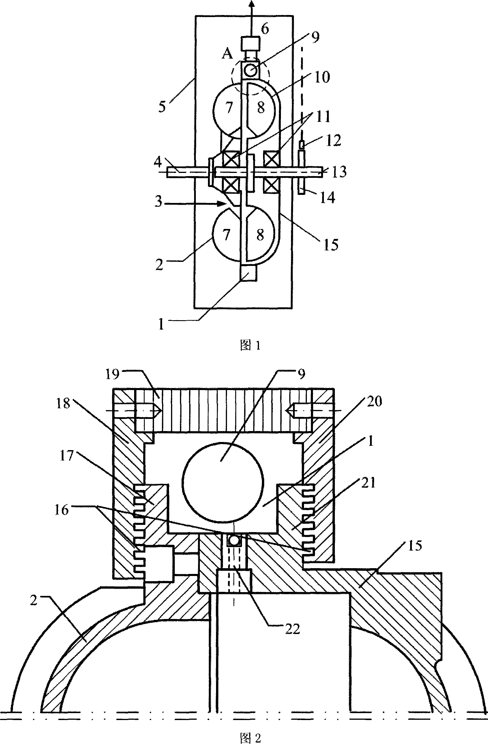
[0014] As shown in Figures 1 and 2: the present invention includes: a centrifugal diversion groove 1, a pump wheel 2, an oil inlet connecting pipe 3, a driving shaft 4, a box body 5, an oil outlet connecting pipe 6, a turbine 10, a bearing 11, Speed ​​sensor 12, driven shaft 13, speed measuring gear 14, rotary casing 15, labyrinth oil seal 16, pump wheel flange 17, left sealing end face 18, oil sealing ring 19, right sealing end face 20, rotary casing flange 21, nozzle 22 .

[0015] The driving shaft 4 is connected to the output shaft of the prime mover, the driven shaft 13 is connected to the working machine, the entire coupling body is suspended on the shaft of the prime mover and the working machine, and the pump wheel flange 17 is connected to the rotary casing flange 21 by bolts. The pump wheel method The flange 17 is integrated wit...


PUM


Abstract

A main body structure of a hydrodynamic coupler with centrifugal diversion and intelligent speed adjustment belongs to the technical field of energy-saving and hydrodynamic transmission. The structure comprises a pump wheel, a pump wheel flange, a turbine, a driving shaft, a driven shaft, a case body, oil inlet/outlet connecting tubes, a rotation speed sensor, a speed-measuring gear, a rotating shell, a rotating shell flange, nozzles, left and right sealed end surfaces and an oil seal ring. Based on the principle of centrifugal diversion, the working oil is led out of the nozzles arranged on the rotating shell and cooled under the centrifugal action, and the quantity and aperture of the nozzles are determined by the type and the load characteristics of the coupler, so as to improve the load adaptability of the coupler. The labyrinth oil seal in axial arrangement can greatly reduce the leakage at the seals, and help the coupler reduce energy loss and improve the controllability of rotation speed and stability of operation. The coupler is externally supported to prevent the case body from bearing the self-weight of the coupler and the case body is only used for storing oil. The invention also has the advantages of small wall thickness and size, compact overall structure, reduced material consumption and good social and economic benefits.

Description

technical field [0001] The invention relates to a speed-regulating hydraulic coupling, in particular to a body structure of a coupling body that adopts a labyrinth oil seal and a centrifugal flow diversion intelligent speed-regulating hydraulic coupling that extracts working oil from a nozzle, which belongs to energy-saving and hydraulic transmission. technology field. Background technique [0002] At present, there are many traditional speed-regulating hydraulic couplings, and their common feature is that a certain amount of working oil is filled in the working chamber of the hydraulic coupling, and the pump wheel obtains mechanical energy from the prime mover, converts it into liquid energy, flows to the turbine and Make it rotate, the turbine converts the liquid energy into mechanical energy output, and repeats itself, realizing the energy transfer from the prime mover to the working machine. Usually, the speed regulation of the speed-regulating hydraulic coupling is rea...

Claims


Application Information

Patent Timeline
Patent Type & Authority Applications(China)
IPC IPC(8): F16H41/02F16H41/24F16H41/30
Inventor 黄刘琦陈红辉刘德均邓真全杨桂康马建民
Owner SHANGHAI JIAO TONG UNIV
Why Eureka
Try Eureka