Liquid pipeline packaged type connecting method and its device

A liquid pipeline and connection method technology, applied in the direction of pipes/pipe joints/fittings, pipes, branch pipelines, etc., can solve the problems of complex structure, inconvenient manufacturing and installation, etc., and achieve improved mechanical strength, convenient installation and construction, and cost. low effect

Inactive Publication Date: 2008-07-09
天津北洋油泵油嘴有限公司
View PDF0 Cites 8 Cited by
  • Summary
  • Abstract
  • Description
  • Claims
  • Application Information

AI Technical Summary

Problems solved by technology

But no matter which way, there are technical problems such as complex structure, inconvenient manufacture and installation.

Method used


Image

  • Liquid pipeline packaged type connecting method and its device
  • Liquid pipeline packaged type connecting method and its device
  • Liquid pipeline packaged type connecting method and its device

Examples


Embodiment 1

[0034] Liquid pipe sleeve connection method, the liquid main pipe is drilled out of the hole, and the platform is milled out around the drilled hole. The connecting head of the main pipe is set, and the connecting head and the branch pipe are connected by threads. Gaskets are used to seal the connection between the branch pipe and the main pipe hole. The branch pipe and the main pipe are sealed and connected with the corresponding hole of the main pipe through the sleeve connector to realize the communication between the branch pipe and the main pipe.

Embodiment 2

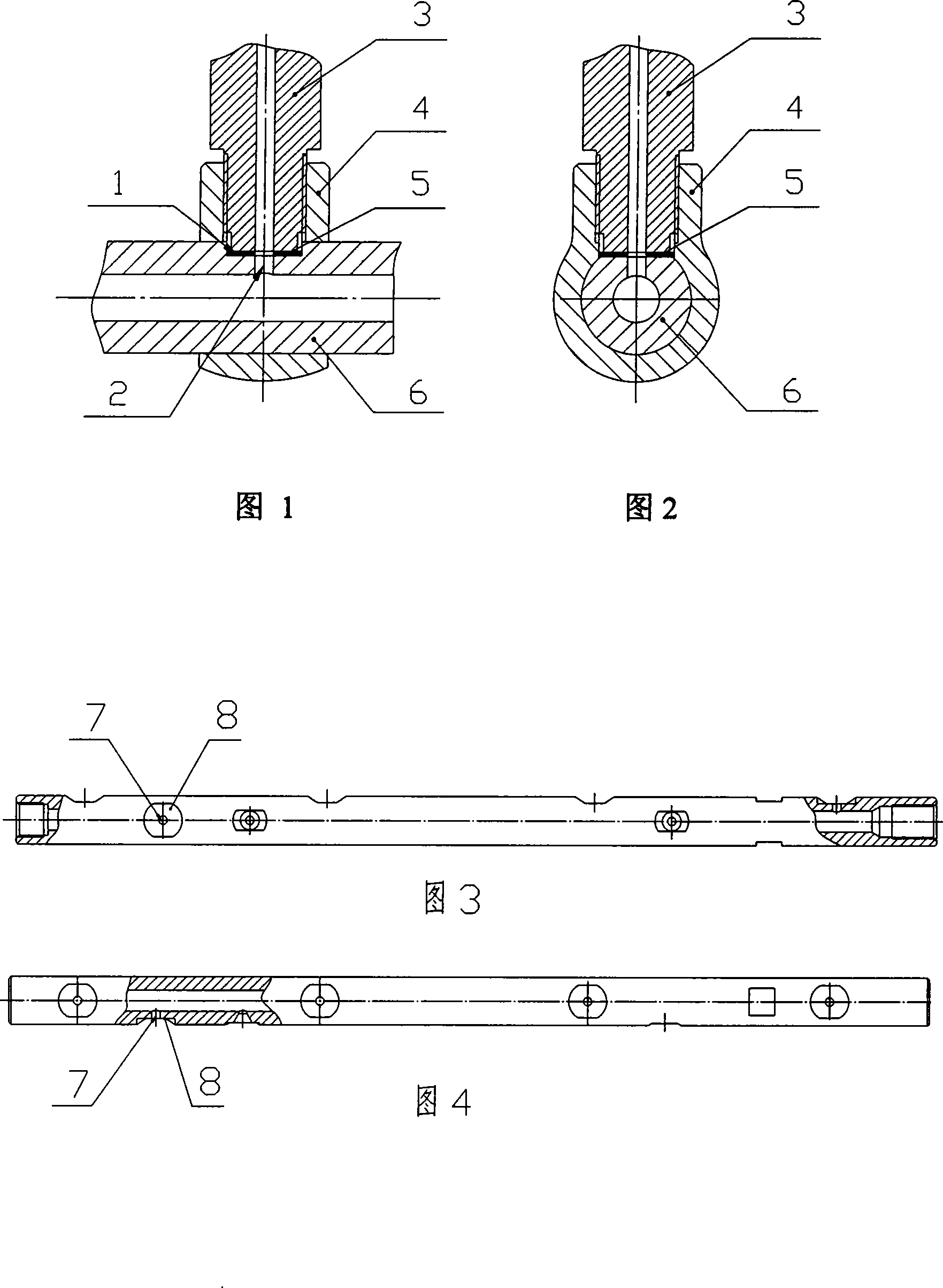
[0036] See Figures 1 and 2. The liquid pipeline set connection device has a milling platform 1 on the outer circle of the main oil pipe 6, and an oil hole 2 is drilled on the platform 1. The branch pipe 3 and the main oil pipe 6 are connected by a sleeve joint 4, and the sleeve joint 4 is set on the On the main oil pipe 6, the sleeve joint 4 and the branch pipe 3 are connected in a threaded structure. A sealing gasket 5 is installed between the branch pipe and the main pipe hole. The sleeve connector connects the branch pipe with the corresponding sealing fitting of the main pipe hole.

Embodiment 3

[0038] The application of the liquid pipeline sleeve connection on the high-pressure common rail pipe of the EFI diesel engine.

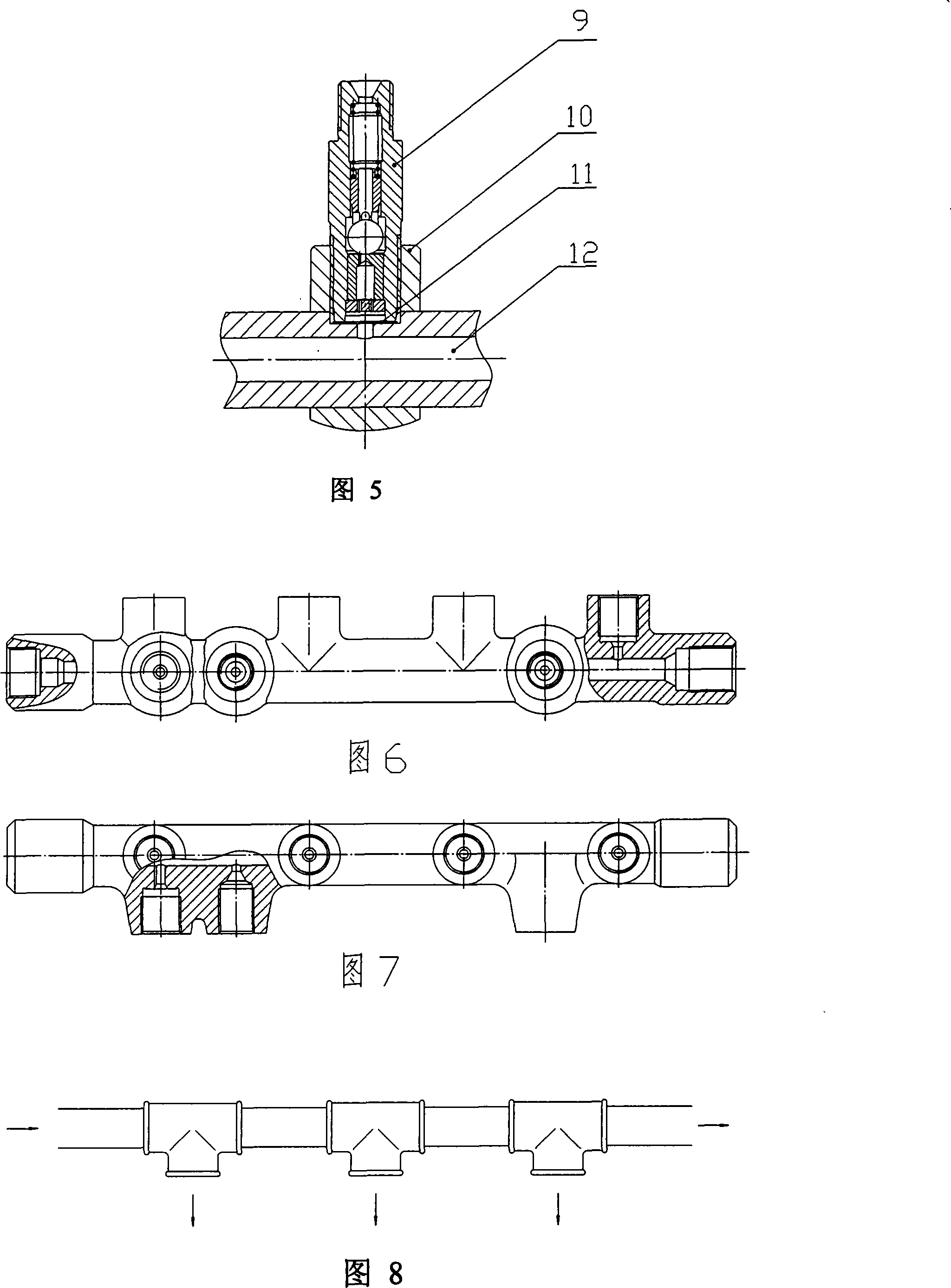
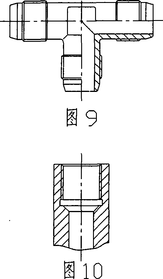
[0039] Figure 6 and Figure 7 show the traditional one-piece common rail pipe. Its main pipe, oil inlet joint, oil outlet joint, safety valve joint, and oil pressure sensor joint are made of cast steel to form a whole. Oil pipe joint (connected to high-pressure pump), flow limiting valve (connected to fuel injector), safety valve (drain oil when oil pressure is too high) and oil pressure sensor. The common rail pipe accepts the high-pressure fuel from the high-pressure pump, and the fuel pressure is above 120MPa. The traditional common rail pipe is made of cast steel. Since the cast steel is prone to defects such as pores, sand holes, and shrinkage porosity, the scrap rate is high.

[0040] The application structure of the present invention on the high-pressure common rail pipe of the electric injection diesel engine. See Figure 3, Figure 4, Figure ...


PUM


Abstract

The invention relates to a method for the sleeve joint of liquid pipelines and a device thereof. The invention belongs to the technical field of hydraulic systems. The liquid pipeline sleeve joint method is characterized in that a main tube has holes, branch tubes or valves are in sleeve joint with the main tube, and the branch tubes or valves are hermetically assembled with the corresponding holes of the main tube by sleeve joint fasteners to realize the communicated with between the branch tubes or valves and the main tube. The liquid pipeline sleeve joint device is characterized in that the main tube is provided with holes, the branch tubes or valves are connected with the main tube by the sleeve joint fasteners, and the sleeve joint fasteners are sleeved around the main tube and tightly connected with the branch tubes or valves, so that the branch tubes or valves are the corresponding holes of the main tube. The invention has the advantages of simple structure, easy fabrication and installation, high mechanical strength, easy construction, high rate of finished products, and low system cost.

Description

technical field [0001] The invention belongs to the technical field of hydraulic systems, and in particular relates to a liquid pipeline sleeve connection method and a device thereof. Background technique [0002] In the hydraulic transmission system, this situation is often encountered, that is, several places need to absorb hydraulic power from the main pipeline at the same time, that is, several branches must be separated from the main pipeline to meet the needs of various places. The transmission structure shown in Figure 8 is often used in traditional hydraulic systems. If there are several branches, the main pipe needs to be cut into several sections, and several three-way joints are required to introduce the hydraulic power of the main pipe into each branch. Pipe thread plus sealing packing connection, ferrule or flared tee joints are often used in high-pressure hydraulic transmission systems, and the ends of the main pipe and branch pipes must also match it, as show...

Claims


Application Information

Patent Timeline
Patent Type & Authority Applications(China)
IPC IPC(8): F16L41/12
Inventor 王宏生苏长波张宏伟信幼平李娟
Owner 天津北洋油泵油嘴有限公司
Why Eureka
Try Eureka