Measuring apparatus for measuring bearing and its part surface appearance

A surface topography and measuring instrument technology, applied in the field of measurement, can solve the problems that the linearity of the guide rail cannot truly meet the measurement requirements, the Z direction cannot be measured and positioned, and the high-precision measurement cannot be truly achieved.

Inactive Publication Date: 2008-07-09
LUOYANG BEARING SCI & TECH CO LTD
View PDF0 Cites 29 Cited by
  • Summary
  • Abstract
  • Description
  • Claims
  • Application Information

AI Technical Summary

Problems solved by technology

[0004] 1. The measurement parameters are single, which cannot meet the requirements of modern manufacturing technology
Domestic similar instruments generally only measure a single parameter such as profile or roughness, which cannot meet the needs of various types of domestic users; the measurement parameters of similar foreign instruments cannot meet the requirements of domestic standards
[0005] 2. Some manufacturers introduced and surveyed early foreign instruments. The resolution of the instrument measurement system is generally 0.01 μm, and the accuracy of the guide rail is below 1 μm / 40mm, which can only meet the measurement requirements of general precision parts. The main technical indicators are quite different from those of foreign countries.
[0006] 3. Large-scale high-precision measurement in the Z direction and sensor positioning in the Z direction cannot be performed, and the functions are difficult to expand, and high-precision measurement cannot be truly realized in a small range; the grating ruler selected in the X direction has a small range and low precision, and cannot meet domestic rough The standard requirements for degree measurement; due to the defects in precision manufacturing, the linearity of the guide rail cannot really meet the measurement requirements; the Z direction cannot measure the positioning

Method used


Image

  • Measuring apparatus for measuring bearing and its part surface appearance
  • Measuring apparatus for measuring bearing and its part surface appearance

Examples


Embodiment Construction

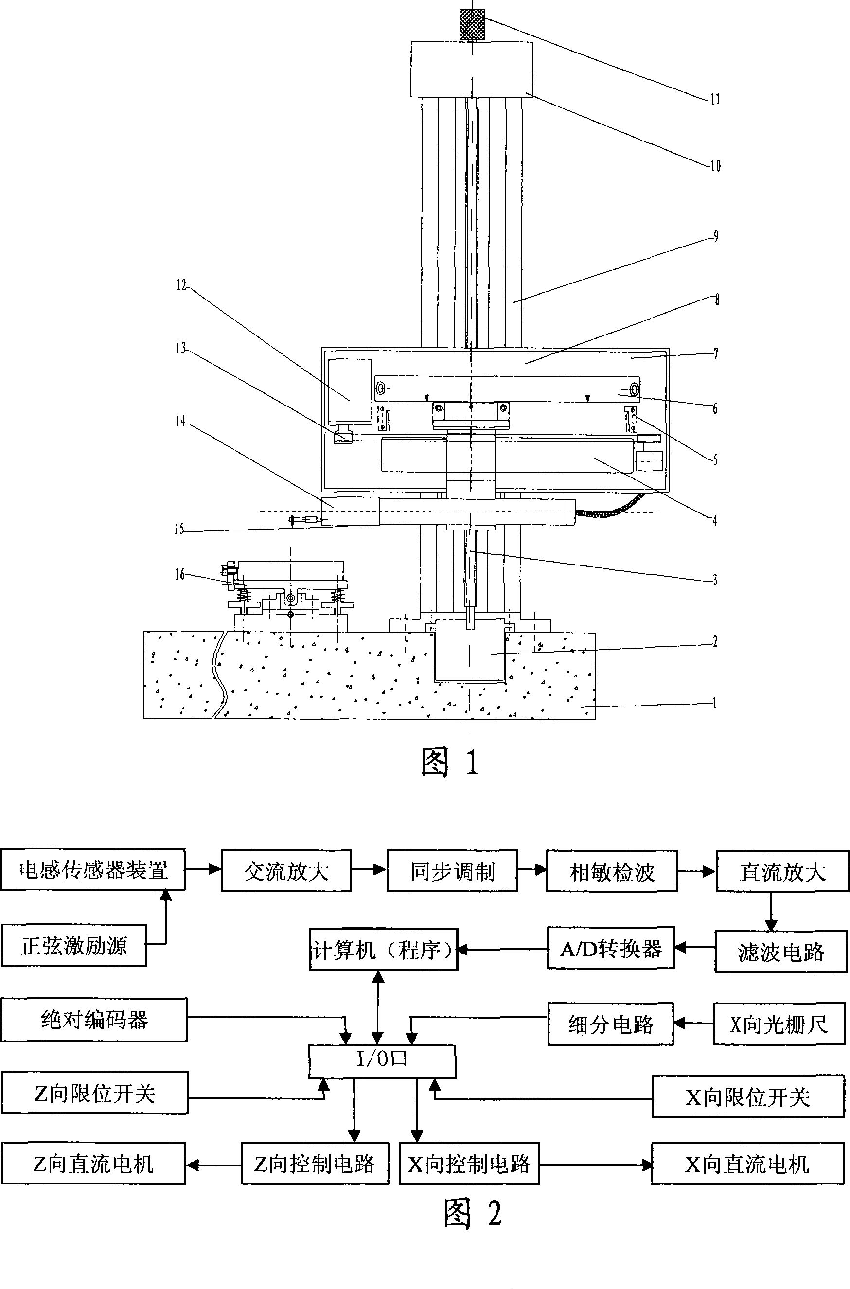
[0025] As shown in Figures 1 and 2: the column guide rail (9) is vertically installed on one end of the measurement base (1), the sensor drive box (8) is installed on the column guide rail (9), and the multi-dimensional workbench (16) is installed on the measurement base on the base (1), it can move horizontally left and right; the diamond stylus (17) is inserted into the inductance sensor device (14) at the lower end of one side of the sensor drive box (8), facing the multi-dimensional workbench (16), it can be moved on the X-direction motor Driven by (12), it moves horizontally along the X-direction rail (4) through the X-direction pulley and toothed belt (13). The moving distance is collected by the X-direction signal acquisition grating (6) and the signal is subdivided and synchronized. into the computer, and the sensor is limited by the X-direction limit switch (5) during the left and right movement; the sensor drive box (8) is installed on the lead screw nut in the ball s...


PUM


Abstract

A measuring apparatus for measuring surface topography of bearing and other parts comprises a pedestal (1), an absolute encoder (2), a ball screw (3), an X-axis sliding guide track device (4), an X-axis limit switch (5), an X-axis signal collection grating (6), a driving box supporting plate (7), a sensor driving box (8), an upright guide track (9), a Z-axis motor (10), a Z-axis manual adjusting knob (11), an X-axis motor (12), an X-axis belt wheel and cog belt (13), an inductive sensor device (14), a sensor coupling rod (15), a multi-dimensional workbench (16) and an electrical system. The invention can measure more than 100 parameters, including profile, waviness, roughness, peak height, valley deepness, total height, average deviation, gradient, slope, bearing length ratio and others; provides detection reference for users to perform various technical analyses to the workpiece to be measured; and can add certain measurement parameter at any time according to the requirement of users.

Description

technical field [0001] The invention belongs to the technical field of measurement, and in particular relates to a measuring instrument which can be used to measure the surface topography of bearings and other parts. Background technique [0002] The machinery industry has achieved 0.001μm feed technology and 0.005μm machining accuracy, which requires detection technology to adapt to it. It is of great social significance to develop surface topography measuring instruments to meet the requirements of advanced manufacturing technology. [0003] At present, the traditional domestic measuring instruments for measuring surface topography such as contour, waviness and roughness have the following defects: [0004] 1. The measurement parameters are single, which cannot meet the requirements of modern manufacturing technology. Domestic similar instruments generally only measure a single parameter such as profile or roughness, which cannot meet the needs of various types of domesti...

Claims


Application Information

Patent Timeline
Patent Type & Authority Applications(China)
IPC IPC(8): G01B7/00G01B7/28G01B7/34G01B11/02
Inventor 朱孔敏宋晓波李国斌刘金秀江纯青熊子健张慧廖家祥高宇
Owner LUOYANG BEARING SCI & TECH CO LTD
Why Eureka
Try Eureka