Device and method for high-precision measurement of large-angle optical wedge angle

A large-angle, high-precision technology, applied in the direction of measuring devices, optical devices, instruments, etc., can solve the problems of questionable measurement accuracy, inconvenient measurement, and many devices, so as to save batch testing time, simple and fast testing methods, The effect of low device cost

Inactive Publication Date: 2020-06-05
SHANGHAI INST OF TECHNICAL PHYSICS - CHINESE ACAD OF SCI
View PDF16 Cites 1 Cited by
  • Summary
  • Abstract
  • Description
  • Claims
  • Application Information

AI Technical Summary

Problems solved by technology

[0003] In the mass processing of optical wedges, it is necessary to measure the wedge angle with high precision and accuracy, especially the wedge angle measurement of large-angle optical wedges is not fast.
The current measurement method is the goniometric method and its related improvement methods. For example, the patent number CN201810961946 provides a method and device for detecting the angle of a transparent wedge, which is calculated by measuring the size of the light spot before and after the wedge by using a prism and two CCDs. Wedge angle, this method requires the adjustment of the turntable during the test process, which introduces related reading errors, and the process is cumbersome and repetitive, which is not conducive to personnel operation and efficiency improvement
This method uses a lot of devices, and there is a case where the light spot is elliptical due to the eccentricity of the CCD spatial position, and the measurement accuracy is open to question.

Method used


Image

  • Device and method for high-precision measurement of large-angle optical wedge angle
  • Device and method for high-precision measurement of large-angle optical wedge angle
  • Device and method for high-precision measurement of large-angle optical wedge angle

Examples


Embodiment Construction

[0044] The implementation examples of the method of the present invention will be described in detail below in conjunction with the accompanying drawings.

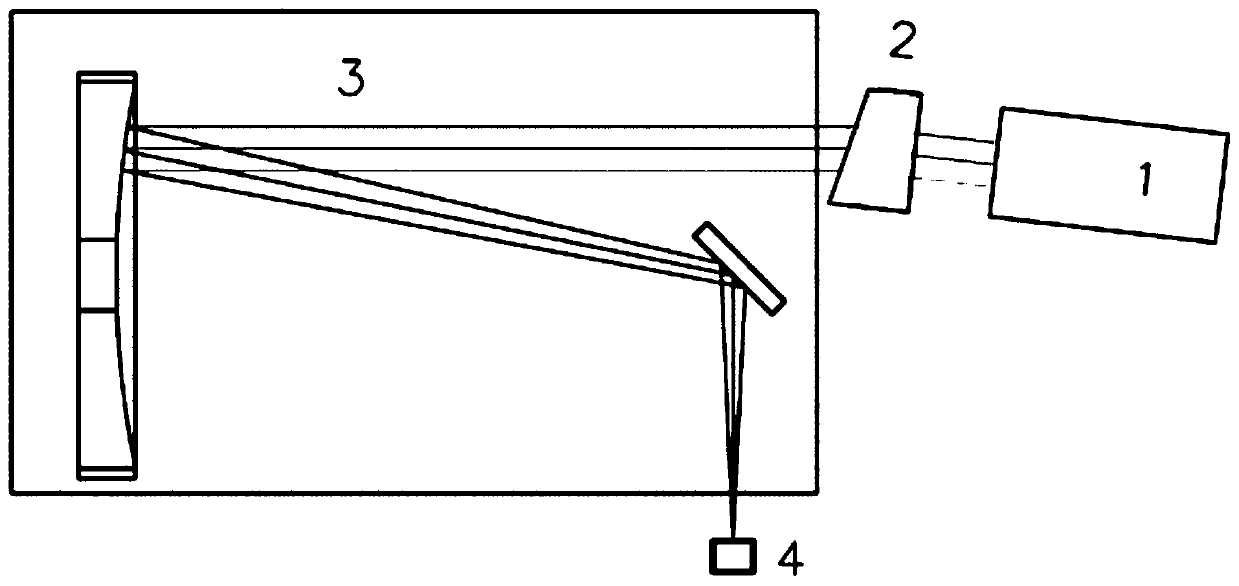
[0045] The main devices adopted in the present invention are described as follows:

[0046] 1. Collimated laser light source 1: The collimated laser light source 1 is composed of single-mode fiber, collimating lens and fiber laser. The fiber adopts the single-mode fiber of Thorlabs company model SM600, and its main performance parameters: the working band is 600-900nm The fiber mode field diameter is 4.6um@680nm, the cladding core diameter is 125±1um, and the cut-off wavelength is 550±50nm; the collimating lens adopts the collimating mirror of Thorlabs company model F810FC-635, and the focal length of the collimating mirror is 35.4mm. The wavelength used is 635nm; the laser adopts the laser diode of Thorlabs company model LPS-PM635-FC, and the laser wavelength is 635nm;

[0047] 2. Optical wedge 2 with a rotating structure:...


PUM

PropertyMeasurementUnit
refractive indexaaaaaaaaaa

Abstract

The invention discloses a device and a method for high-precision measurement of a large-angle optical wedge angle, and the device and method are based on the principle that an optical wedge enables alight beam to generate fixed angle deflection, and obtain the angle deviation of the large-angle optical wedge angle through the measurement of the deflection angle of the light beam. The device is composed of a collimated laser light source, a to-be-detected optical wedge with a rotating structure, a collimator and an area array CCD assembly, and the collimated laser light source is refracted bythe optical wedge and then converged on an area array CCD of a focal plane through the collimator. The to-be-detected optical wedge is rotated, and the angle of the optical wedge is accurately measured through the rotation angle and the light spot position change on the area array CCD. The device is simple in structure, low in cost, simple in detection method and suitable for batch production andhigh-precision measurement of optical devices such as optical wedges and parallel flat plates.

Description

technical field [0001] The invention relates to the measurement and calibration of optical wedge parameters, in particular to a device and method for measuring the wedge angle of a large-angle optical wedge with high precision. Background technique [0002] An optical wedge refers to a refracting prism with a certain angle between the front and rear surfaces, also known as a wedge mirror. Because the optical wedge has the effect of deflecting the beam at a fixed angle, it can usually be used to split light or pass through optical elements such as windows. Taking advantage of its property of changing the propagation direction of light beams, the optical wedge has a wide range of applications. For example, an optical wedge can be used as a laser to extract light, and part of the light can be intercepted from the laser light path as a reference light. It can also be used as the output mirror of the oscillator cavity to avoid the influence of the light emitted from the rear su...

Claims


Application Information

Patent Timeline
Patent Type & Authority Applications(China)
IPC IPC(8): G01B11/26
CPCG01B11/26
Inventor 吴金才窦永昊张亮何志平
Owner SHANGHAI INST OF TECHNICAL PHYSICS - CHINESE ACAD OF SCI
Why Eureka
Try Eureka