Device and method of super-resolution imaging

A super-resolution and low-resolution image technology is applied in the field of devices for realizing super-resolution imaging, which can solve the problems of increasing system structure and control complexity, and achieve the effects of low cost, simple control and simple structure.

Inactive Publication Date: 2008-07-09
TSINGHUA UNIV +1
View PDF4 Cites 20 Cited by
  • Summary
  • Abstract
  • Description
  • Claims
  • Application Information

AI Technical Summary

Problems solved by technology

However, the position of the image plane after micro-zooming will change, and focus compensation is required; and at different focal lengths...

Method used


Image

  • Device and method of super-resolution imaging
  • Device and method of super-resolution imaging
  • Device and method of super-resolution imaging

Examples


Embodiment Construction

[0045] The device and method for realizing super-resolution imaging using the micro-rotation method of the present invention will be further described in detail in conjunction with the accompanying drawings and specific embodiments:

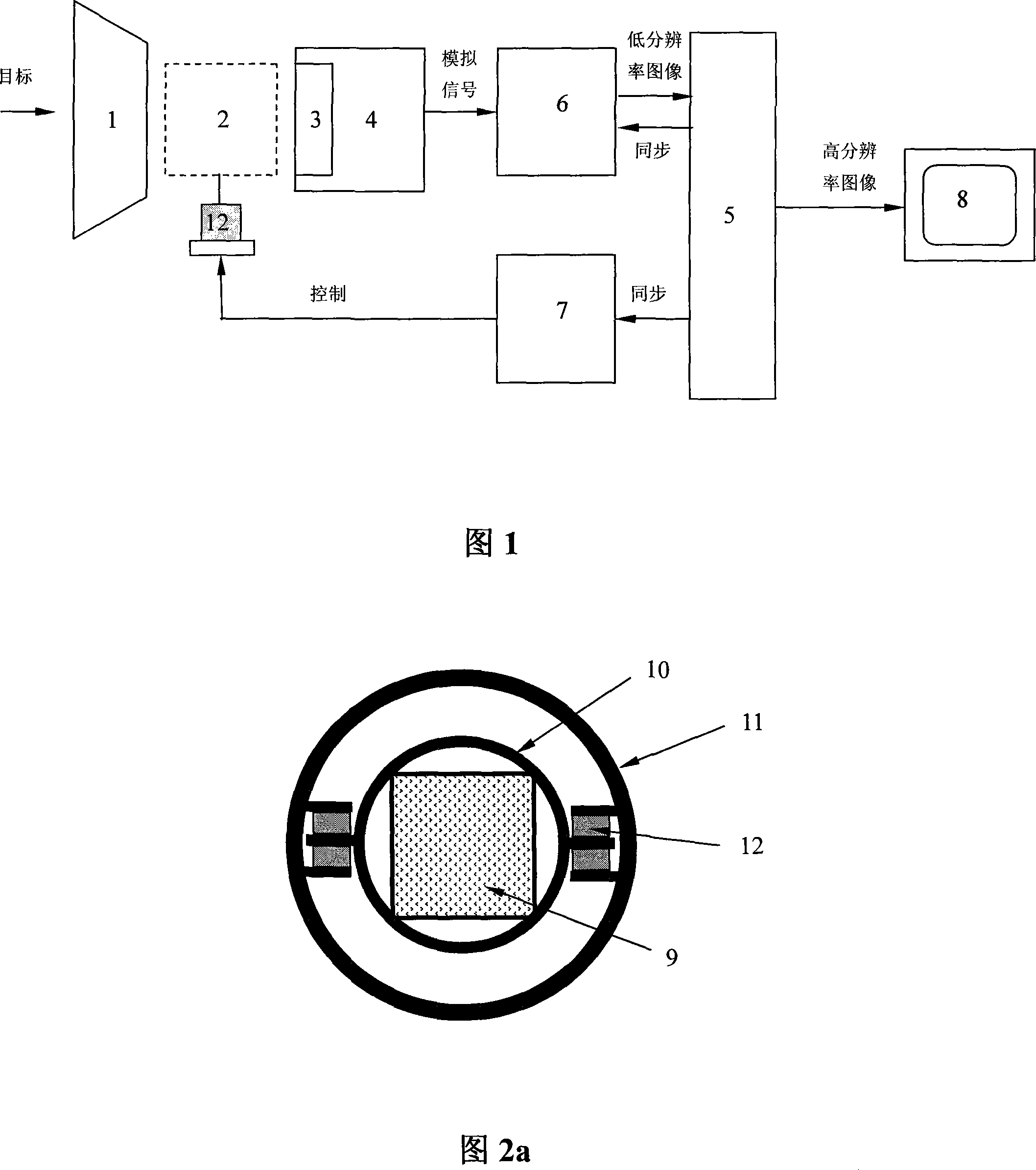
[0046] Fig. 1 is a kind of device system block diagram that utilizes micro-rotation method to realize super-resolution imaging, consists of optical imaging objective lens 1, transfer mechanism 2 and its control circuit 7, piezoelectric ceramic drive device 12, photodetector array 3 and its readout Output circuit 4, analog-to-digital conversion circuit 6, signal processing and synchronization circuit 5 and display device 8. The image transfer mechanism 2 can be arranged in front of the optical imaging objective lens 1 , between the optical imaging objective lens 1 and the photodetector array 3 or inside the optical imaging objective lens 1 .

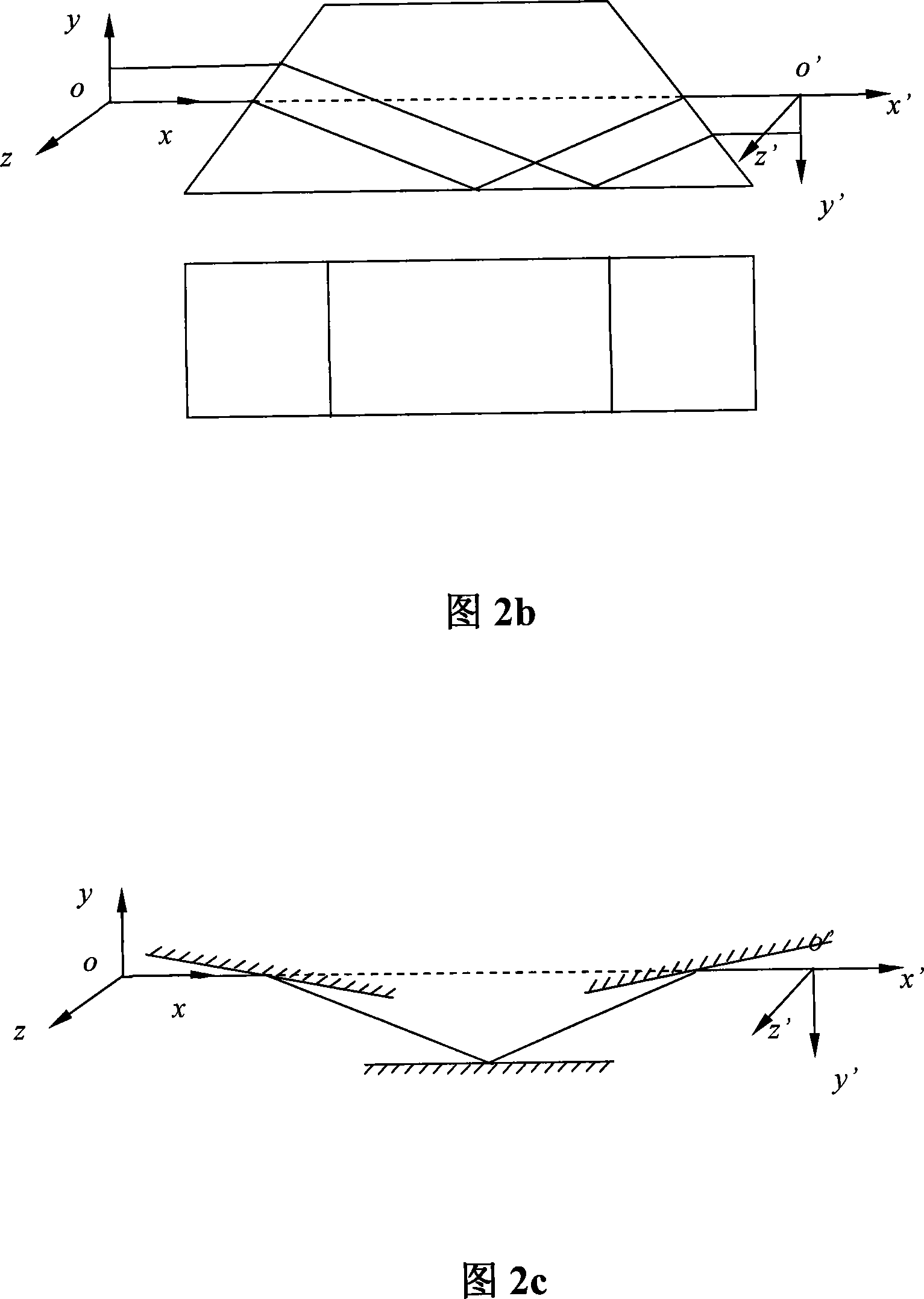
[0047] Fig. 2a is a cross-sectional schematic diagram of the image transfer mechanism 2 in the embodiment...


PUM


Abstract

A super-resolution imaging device and a method are provided, which relate to a device and a method to realize super-resolution imaging by means of a micro rotation method. A series of low resolution images with relatively micro rotation are obtained by controlling a reversed image mechanism or slightly rotating photodetector array; the gray value of per-pixel of low resolution images is taken as linear sum of the gray value of all pixels in corresponding relevant area on super-resolution images to be obtained; a linear equation is listed for the gray value of per-pixel of low resolution images and the linear equations are simultaneous to obtain sparse linear equations and the least squares solution is the super-resolution image rebuilt by super-resolution. Compared with the existing micro scanning, micro zooming super-resolution imaging technology, the micro rotation method only controls the reversed image mechanism and ensures that the photodetector array slightly rotates, the structure is simpler, control is more convenient and the realization cost is much lower.

Description

technical field [0001] The invention relates to a device and method for realizing super-resolution imaging, belonging to the technical field of photoelectric imaging. Background technique [0002] In recent years, photoelectric imaging technology has developed rapidly and is widely used in military, security, remote sensing, search and rescue and many other fields. Obtaining high-resolution digital images is an unremitting pursuit of people. However, due to the limited geometrical size of the detector units of the photoelectric imaging system and the existence of the distance between the detector units, the acquired digital images are blurred and confused. Especially for infrared imaging detectors, the geometric size of the detector unit is relatively large, and the number of detector units is small. The common ones are 320×240 pixels and 640×480 pixels. Such low image resolution often cannot meet the needs of military reconnaissance and battlefield surveillance. , remote s...

Claims


Application Information

Patent Timeline
IPC IPC(8): H04N5/33G02B26/10
Inventor 周峰李光伟王东生张海涛刘永坚闫海赵达尊
Owner TSINGHUA UNIV
Why Eureka
Try Eureka