
Non-contact type dynamic measuring device and method for wheel diameter based on laser and method thereof

A dynamic measurement and non-contact technology, applied in the field of optical measurement, can solve problems such as low measurement accuracy, wear of measuring instruments and wheels, and small operating space, and achieve the effects of simple data processing, dynamic measurement, and improved response speed

Active Publication Date: 2008-07-16
BEIJING JIAOTONG UNIV
View PDF8 Cites 52 Cited by
  • Summary
  • Abstract
  • Description
  • Claims
  • Application Information

AI Technical Summary

Problems solved by technology

However, the instrument still uses the contact measurement method, which causes a certain amount of wear on the measuring instrument and the wheel, and the measurement point is easily affected by oil and debris on the wheel diameter.
[0006] To sum up, the existing contact measurement technology using calipers or calipers generally has the following disadvantages: (1) relying on manual operation, the measurement efficiency is low, and it is not easy to find problems in time; (2) the measurement accuracy is easily affected by the external environment; ( 3) The wheel must be disassembled, and the measurement cycle is long; (4) Because the operating space on site is too small, this kind of contact measurement technology is generally not suitable for measuring the diameter of the wheel on site
However, the existing non-contact dynamic measurement technology for wheel diameter still has the following problems to be solved: 1. The measuring device is too complicated and difficult to install and debug; 2. The measurement accuracy is not high; 3. The measurement response speed is not high

Method used


Image

  • Non-contact type dynamic measuring device and method for wheel diameter based on laser and method thereof
  • Non-contact type dynamic measuring device and method for wheel diameter based on laser and method thereof
  • Non-contact type dynamic measuring device and method for wheel diameter based on laser and method thereof

Examples


Embodiment Construction

[0049] The invention firstly provides a simple and practical non-contact dynamic measuring device and method for the diameter of train wheels. The measuring device and method thereof are realized based on one or two laser displacement sensors, are very simple to install and use, and are especially suitable for on-line dynamic measurement of wheel diameters when trains are moving.

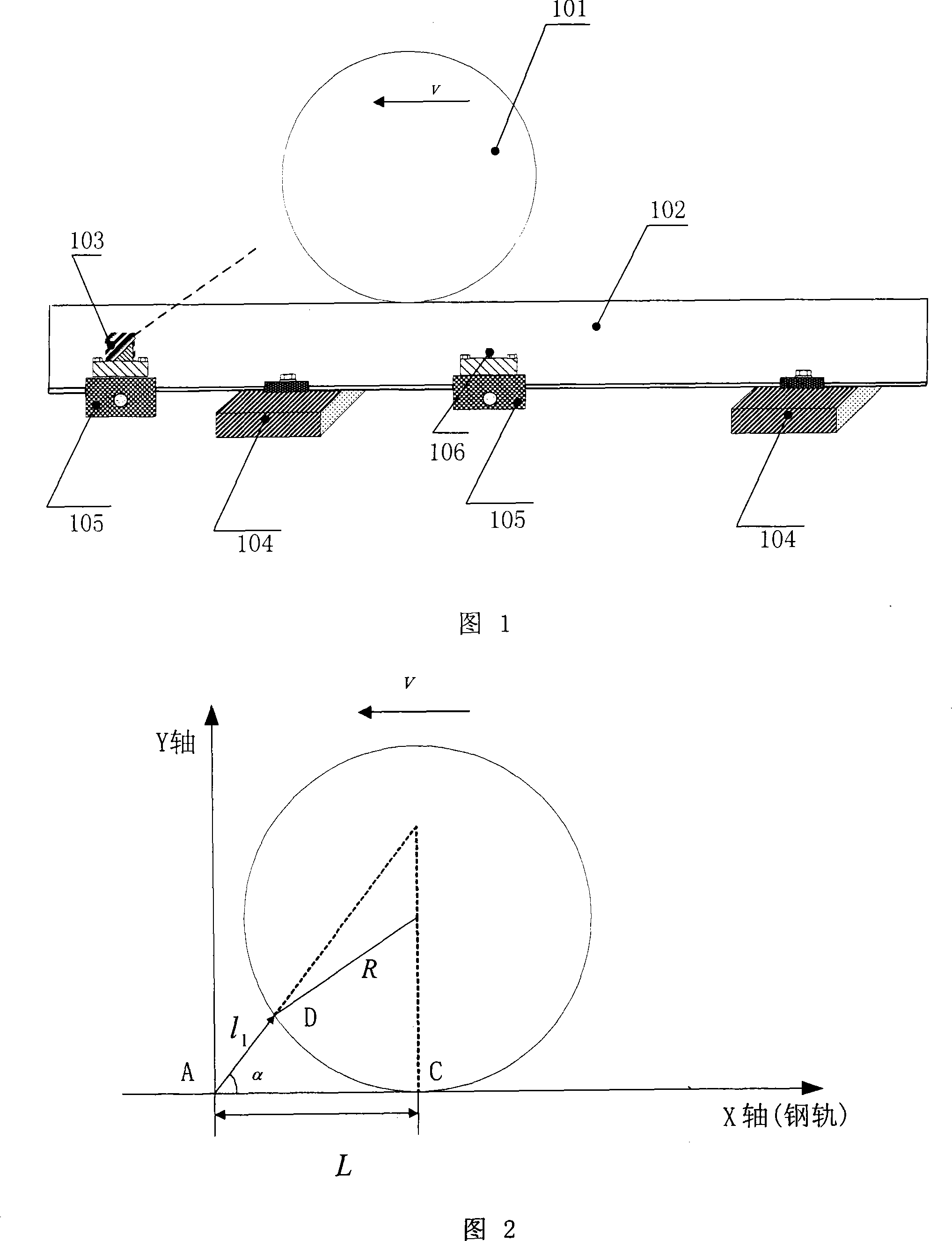
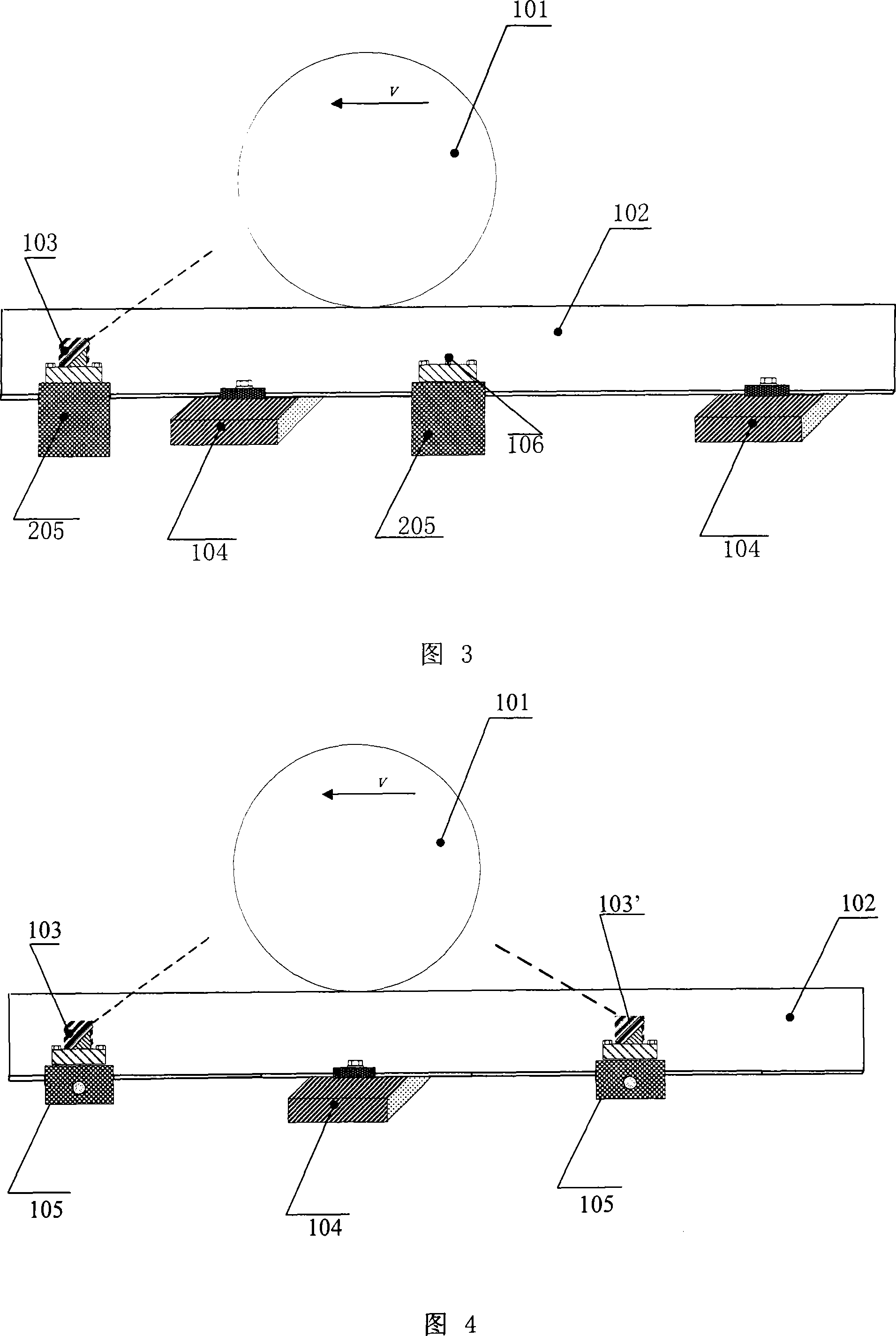
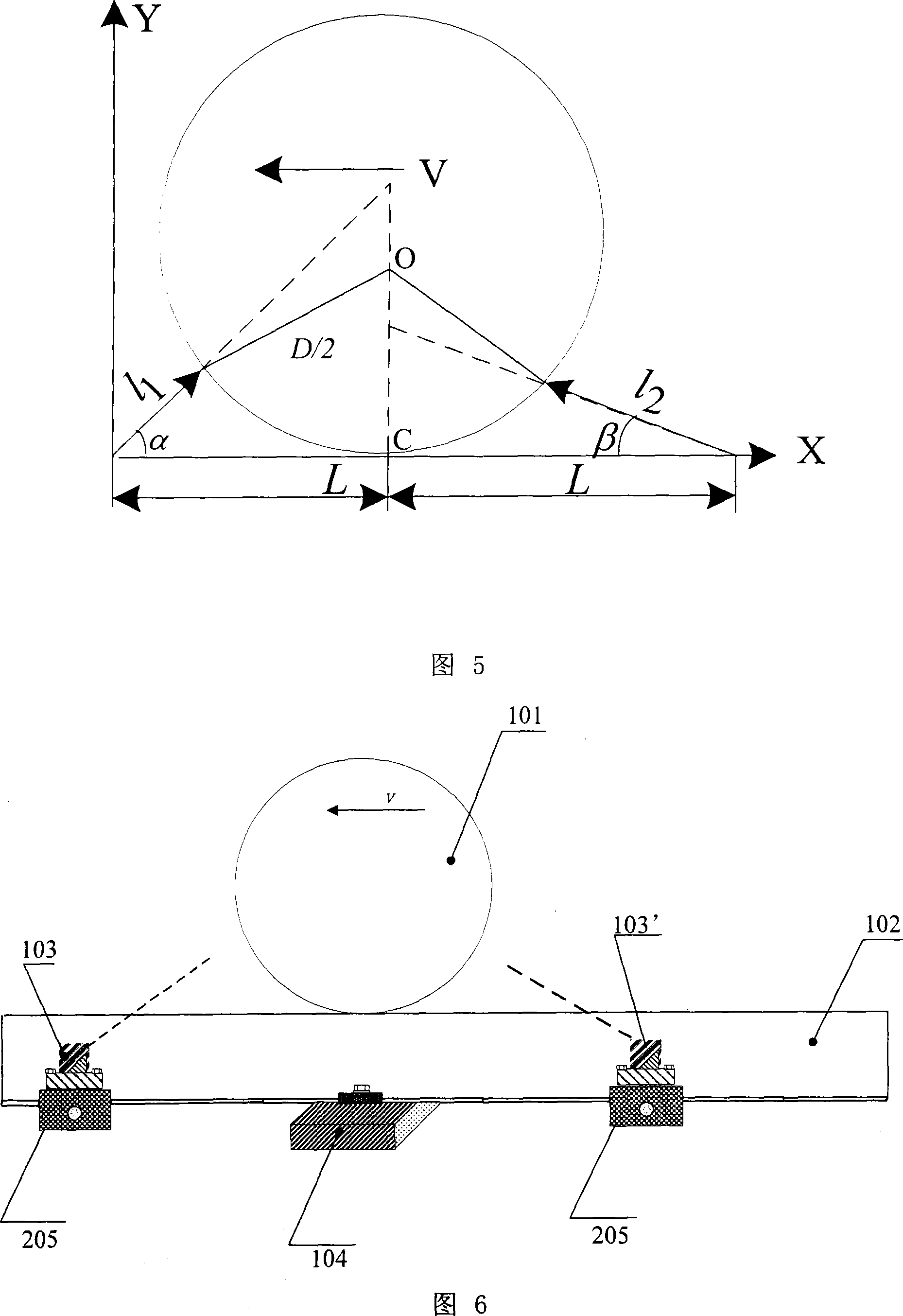
[0050] Fig. 1 shows the first embodiment of the non-contact dynamic measuring device for the wheel diameter. Referring to Fig. 1, this embodiment is a non-contact wheel diameter dynamic measurement device using a single laser displacement sensor, specifically including: a laser displacement sensor 103, a wheel alignment sensor 106 and a central processing unit (not shown). Both the laser displacement sensor 103 and the wheel alignment sensor 106 are fixed on the rail 102 through the block 105 or directly by bonding, and are located on the outside (or inside) of the rail at the same time. A pluralit...


PUM


Abstract

The invention discloses a non-contact dynamic measuring device for a wheel diameter based on laser and a method thereof. The measuring device consists of a laser displacement sensor, a wheel positioning sensor or two laser displacement sensors; the two sensors are arranged along the direction of a steel rail. When the two laser displacement sensors are applied, light spots of irradiation laser can directly irradiate onto two opposite surfaces of the measured wheel; the two laser displacement sensors respectively and continuously measure the distance between each sensor and corresponding point on a tread of the wheel; the reading data of distance in each laser displacement sensor is recorded when the sum of the distance measured by the two laser displacement sensors is basically unchanged, to calculate the diameter of the train wheel. The invention requires two sensors at most, and measurement principle is simple and practical.

Description

technical field [0001] The invention relates to a device and method capable of non-contact dynamic measurement of the diameter parameters of train wheels based on laser measurement technology, belonging to the technical field of optical measurement. Background technique [0002] With the development of my country's railway industry, the speed of trains continues to increase, and people pay more and more attention to the safety of vehicle operation. The high-speed running of the train will intensify the wear and tear between the tread of the train wheel and the rail, resulting in changes in the diameter of the wheel, affecting the cooperation between the wheel and the track, and thus affecting the safety of the train. Therefore, after a certain period of time, the train wheels will be regularly inspected, and the wheels whose parameters exceed the limit need to be repaired or scrapped, otherwise it will bring hidden dangers to the safe operation of the train. [0003] In the...

Claims


Application Information

Patent Timeline
IPC IPC(8): B61K9/12
Inventor 冯其波张志峰陈士谦崔建英
Owner BEIJING JIAOTONG UNIV
Learn More