Vertical film lifting mechanism

A vertical, film-rolling technology, applied in the direction of winding strips, sending objects, thin material processing, etc., can solve the problems of uneven surface of film 3, inconvenient film replacement operation, and increased defective rate of finished products.

Inactive Publication Date: 2008-07-16
翔渝实业股份有限公司
View PDF1 Cites 5 Cited by
  • Summary
  • Abstract
  • Description
  • Claims
  • Application Information

AI Technical Summary

Problems solved by technology

[0003] However, for the operation of the front stage conveying device 1 of the above-mentioned manufacturing process, it is a horizontal film feeding method, and the conveying device 1 of the film is horizontally installed at a predetermined position above the mold 2. Therefore, when the film 3 is used up, When the film 3 is used up, the replacement operation of the film is relatively inconvenient, that is, the operator must use an el

Method used


Image

  • Vertical film lifting mechanism
  • Vertical film lifting mechanism
  • Vertical film lifting mechanism

Examples


Embodiment Construction

[0032] In order to illustrate the structure and the achieved effects of the present invention in detail, the following preferred embodiments are given below together with the accompanying drawings.

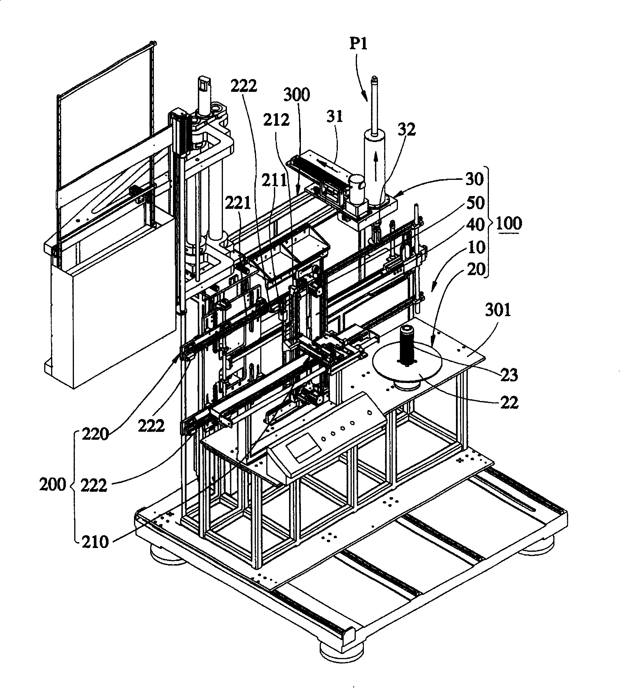
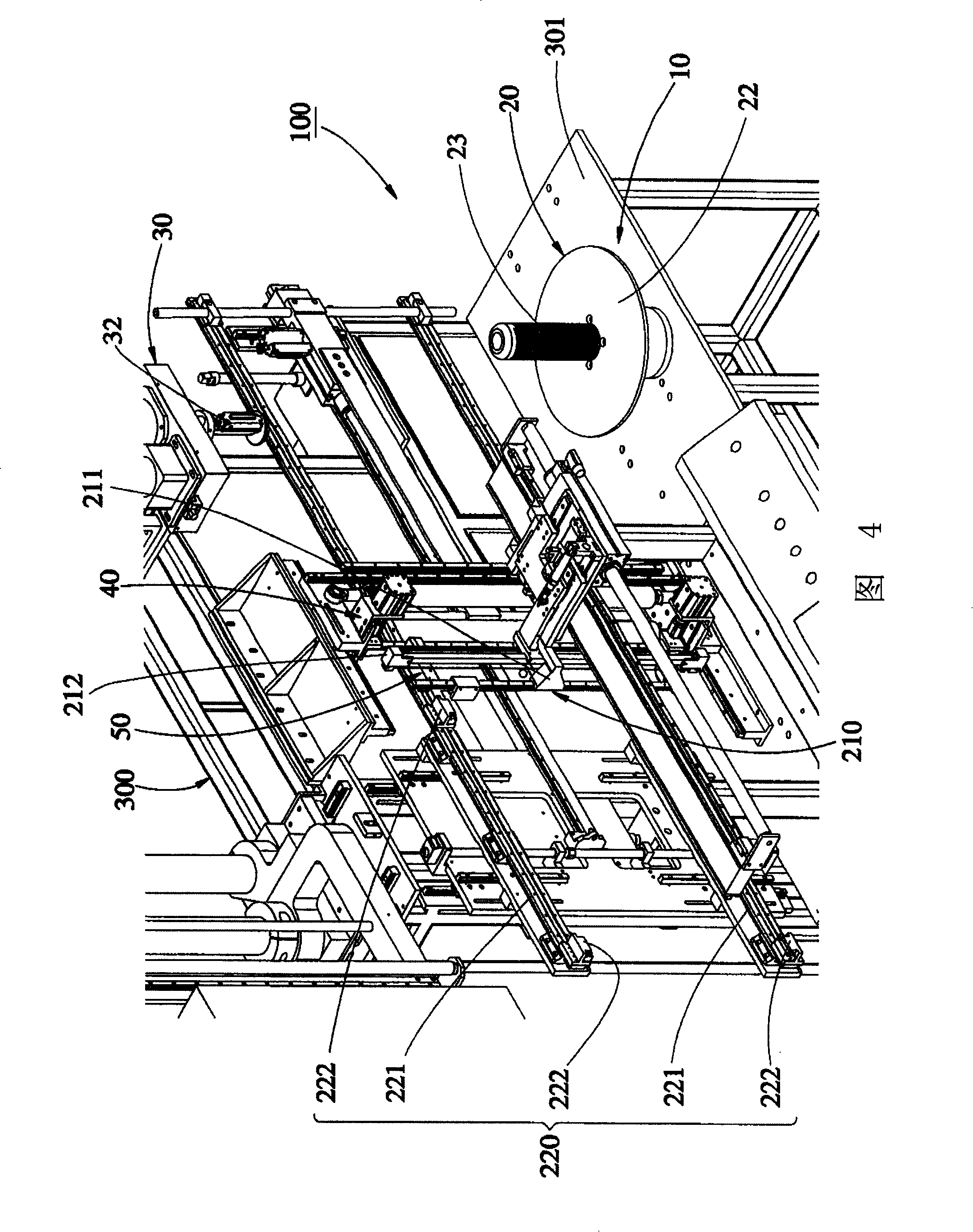
[0033] Such as image 3 ~Shown in Fig. 15, it is a vertical film-on-film mechanism 100 of a preferred embodiment of the present invention. A platform 301, before illustrating the vertical film-on-film mechanism 100 of the present invention, the film-drawing mechanism 200 and roll film 99 that cooperate with this mechanism are introduced as follows:

[0034] Such as image 3 As shown in FIG. 4 , the film pulling mechanism 200 has a film pulling device 210 and a film feeding device 220 that can move relative to the frame 300 . The film pulling device 210 is connected with a film pulling part 211 and a cutting part 212 . The film feeding device 220 has two cantilever arms 221, and the cantilever arm 221 is provided with four grippers 222 (because the film pulling mechanism 200 is not...


PUM


Abstract

The invention relates to an upright filming mechanism, which outputs a coiled film in an upright state; the filming mechanism is arranged on a frame which is provided with a platform; the upright filming mechanism comprises a film base group which is arranged on the frame; the film base group has a supporting component, a compressing component and a driving and rotating component; the supporting component supports the coiled film to be arranged vertical to the platform; the compressing component is arranged above the supporting component, and the compressing component can generate radial movement of expansion and contraction; the driving and rotating component is connected with the compressing component so as to drive the compressing component to rotate; the invention also comprises a rotating group which is arranged on the platform and behind the film base group; the rotating group has at least two rotating shafts vertical to the platform; the coiled film is pulled on the film base group and then wound between the rotating shafts. The invention can combine with a film pulling mechanism for inputting upright films parallelly into a die, ensure that the coiled film is not subject to pulling due to direction change, and facilitate each work item of the film (such as replacement of the entire film coil or part film treatment).

Description

technical field [0001] The invention relates to a conveying device, in particular to a vertical film loading mechanism. Background technique [0002] Film processing and reprocessing operations are often used in the industry, and the front-end conveying device of the film is also closely related to the subsequent film processing and manufacturing process. As shown in Figure 1, it is a film front-end conveying device 1 used for in-mold film combination molding. The conveying device 1 is arranged above a mold 2 outside and has a first pulley 1a and a roller 1b to transfer the rolled The film 3 is input parallel to the mold 2, and there is a matching clamp 4 under the mold 2. The clamp 4 is used to clamp the film 3 conveyed from the conveying device 1, so that the surface of the film 3 is flat, so as to facilitate subsequent injection molding operations. Make the resulting finished product more beautiful. [0003] However, for the operation of the front stage conveying device...

Claims


Application Information

Patent Timeline
IPC IPC(8): B65H16/00B65H20/16B65H35/04B29C31/00B29C45/14
Inventor 余聪文
Owner 翔渝实业股份有限公司
Why Eureka
Try Eureka