
Tricuspid valve prosthesis

A valve prosthesis and tricuspid valve technology, applied in the field of medical devices, can solve the problems of easy falling off, conduction block, original valve leaflet damage, etc., and achieve the effect of firm anchoring, preventing conduction block, and enhancing anchoring force

Pending Publication Date: 2020-11-10
SHANGHAI TRULIVE MEDTECH CO LTD +1
View PDF0 Cites 1 Cited by
  • Summary
  • Abstract
  • Description
  • Claims
  • Application Information

AI Technical Summary

Problems solved by technology

[0005] Although the technology of tricuspid valve replacement is developing rapidly, there are still some recognized difficulties in the design of the valve, for example, 1. The anchoring of the valve
The existing tricuspid valve design basically adopts clipping leaflets or grabbing leaflets for anchoring. These two anchoring methods will pull the tendons and cause damage to the original leaflets.
Some people also proposed to use the atrioventricular septum for anchoring, but this anchoring method is not reliable, and additional leaflets need to be used, otherwise it is easy to fall off, posing a safety hazard
2. There is a risk of conduction block
Anchoring through the main body of the stent, the stent will compress the conduction tissue, and there will be a risk of conduction block

Method used


Image

  • Tricuspid valve prosthesis
  • Tricuspid valve prosthesis
  • Tricuspid valve prosthesis

Examples


Embodiment 1

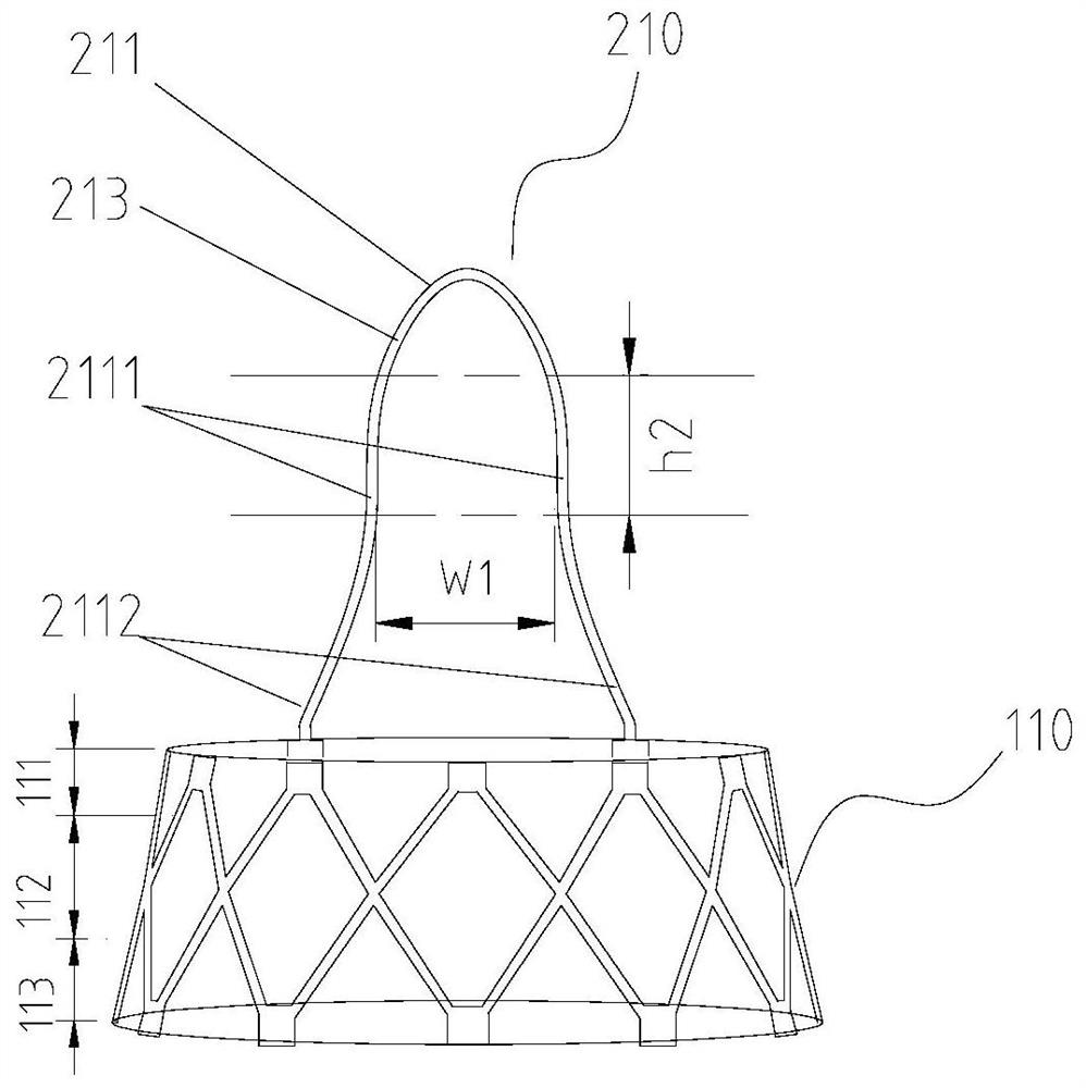
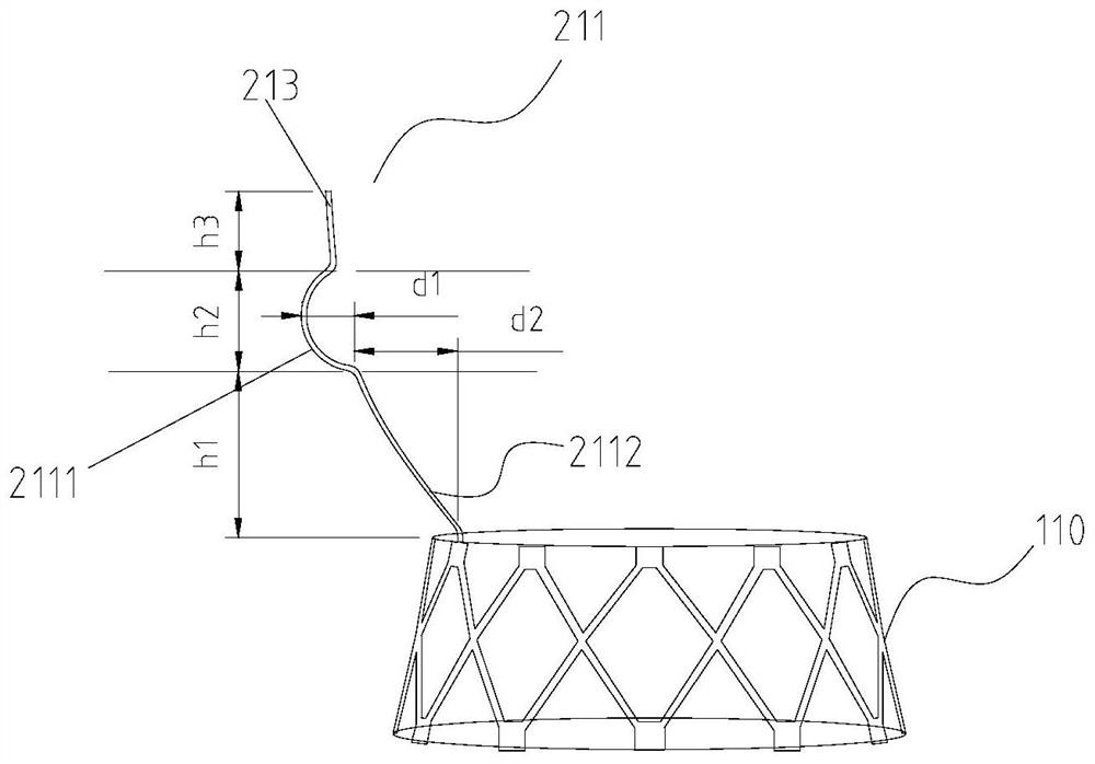
[0050] This embodiment provides a tricuspid valve prosthesis, the valve prosthesis includes a stent body 110, and the stent body 110 is implanted at the annulus of the tricuspid valve to support the artificial valve leaflet; it also includes an anchoring structure 210, which is set Above the stent body 110, it is used to anchor the stent body 110 at the original annulus to prevent its displacement; wherein, the anchoring structure 210 is configured to be partially attached to the fossa ovale of the interatrial septum, by attaching the fossa ovale To form a retaining force, so as to realize the anchoring effect on the valve prosthesis.

[0051] In this embodiment, inspired by the original structure of the fossa ovalis, a new anchoring structure is proposed. The anchoring structure 210 is set in such a way that it is partially embedded in the fossa ovalis and fits the fossa ovalis, and is produced by using the concave structure of the fossa ovalis. Retention force, which prevent...

Embodiment 2

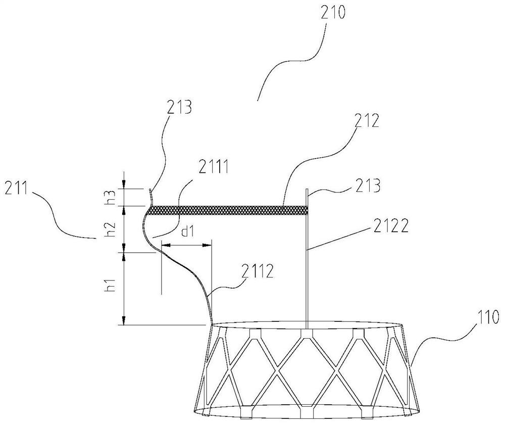
[0067] This embodiment provides a tricuspid valve prosthesis, which is an improvement on the basis of Embodiment 1, wherein the anchoring structure 210 also includes a second anchor 212, see Figure 3-Figure 6 , the second anchor 212 is fixed to the atrial wall by radial force, thereby providing enhanced anchoring for the valve prosthesis.

[0068] see image 3 , Figure 4 , in this embodiment, the first anchor 211 is a rod-shaped structure, and a protrusion 2111 is disposed along the axial direction. The second anchor 212 is disposed at the upper edge of the protrusion 2111, and the second anchor 212 is configured to have an outer protrusion 2121. When implanted, the outer protrusion 2121 is embedded into the egg from the upper edge of the protrusion 2111. The round fossa provides enhanced anchoring, while the force point is on the upper edge of the fossa ovale to prevent damage to the original structure of the fossa ovale.

[0069] Specifically, the second anchoring piece...


PUM


Abstract

The invention discloses a tricuspid valve prosthesis. The tricuspid valve prosthesis comprises a stent main body implanted at a tricuspid valve ring and used for supporting an artificial valve leaflet; and an anchoring structure arranged above the stent main body and used for anchoring the stent main body at a native valve ring to prevent the stent main body from shifting. The anchoring structureis configured to be partially attached to the fossa ovalis of the atrial septum, retention force is formed by attaching the fossa ovalis, and therefore the anchoring effect on the valve prosthesis isachieved. Under the enlightenment of the original structure of the fossa ovalis, the concave structure of the fossa ovalis is fully utilized to partially clamp and fix the anchoring structure in the fossa ovalis, so that a certain retention force is provided, and the valve prosthesis is prevented from shifting during cardiac compression; and according to the anchoring structure, a traditional anchoring mode of clamping the valve leaflet or grabbing the valve leaflet is changed, and the chordae tendineae cannot be pulled or the valve leaflet cannot be damaged.

Description

technical field [0001] The invention relates to the technical field of medical devices, in particular to a valve prosthesis implanted in the heart for replacing the original tricuspid valve. Background technique [0002] Heart valves are membrane-like structures that can open and close in the organs of humans or certain animals. Every human heart has four valves. The aortic valve connects the left ventricle to the aorta, the pulmonary valve connects the right ventricle to the pulmonary artery, the mitral valve connects the left atrium to the left ventricle, and the tricuspid valve connects the right atrium to the right ventricle. They all act as one-way valves, so that blood can only flow from one direction to the other and not back. [0003] With the development of social economy and the aging of the population, the incidence of valvular heart disease has increased significantly. Studies have shown that the incidence of valvular heart disease in the elderly population ove...

Claims


Application Information

Patent Timeline
Patent Type & Authority Applications(China)
IPC IPC(8): A61F2/24
CPCA61F2/2412A61F2/2418A61F2220/0016A61F2310/00023
Inventor 不公告发明人
Owner SHANGHAI TRULIVE MEDTECH CO LTD
Learn More