Prefabricated concrete ground beam-shear wall connecting joint and construction method thereof

A technology of prefabricated concrete and connecting nodes, which is applied in the direction of walls, structural elements, building components, etc., can solve the problems of inability to make full use of assembly type fast and efficient, no fast and efficient detection method, insufficient tensile and shear resistance, etc., to avoid Premature cracking, avoiding tension-shear composite stress, and reducing labor costs

Pending Publication Date: 2021-11-12
CHANGAN UNIV
View PDF0 Cites 0 Cited by
  • Summary
  • Abstract
  • Description
  • Claims
  • Application Information

AI Technical Summary

Problems solved by technology

Sleeve connection has defects such as leakage irrigation, insufficient irrigation and insufficient insertion depth of steel bars in the project, and there is no fast and efficient detection method, so it is difficult to guarantee the force transmission of steel bars
Since the shear wall is generally double-layered and bidirectionally reinforced, the number of steel bars is large, and it is very difficult to align the holes of the steel bars during on-site assembly, and the construction is stagnant
The diameter of steel bars in shear walls is generally small, and the individual pressure bearing capacity is insufficient. Therefore, temporary supports must be installed during the installation of prefabricated shear walls, and the process is cumbersome.
After the steel sleeve butt joint is completed, concrete still needs to be poured twice to solve the problems of vertical pressure bearing and horizontal shear resistance. However, the contact surface between the post-cast concrete and the prefabricated components of this second pouring is easy to crack, and the tensile and shear resistance is insufficient. , unable to take advantage of the fast and efficient characteristics of assembly

Method used


Image

  • Prefabricated concrete ground beam-shear wall connecting joint and construction method thereof
  • Prefabricated concrete ground beam-shear wall connecting joint and construction method thereof
  • Prefabricated concrete ground beam-shear wall connecting joint and construction method thereof

Examples


Embodiment Construction

[0029] The present invention is described in further detail below in conjunction with accompanying drawing:

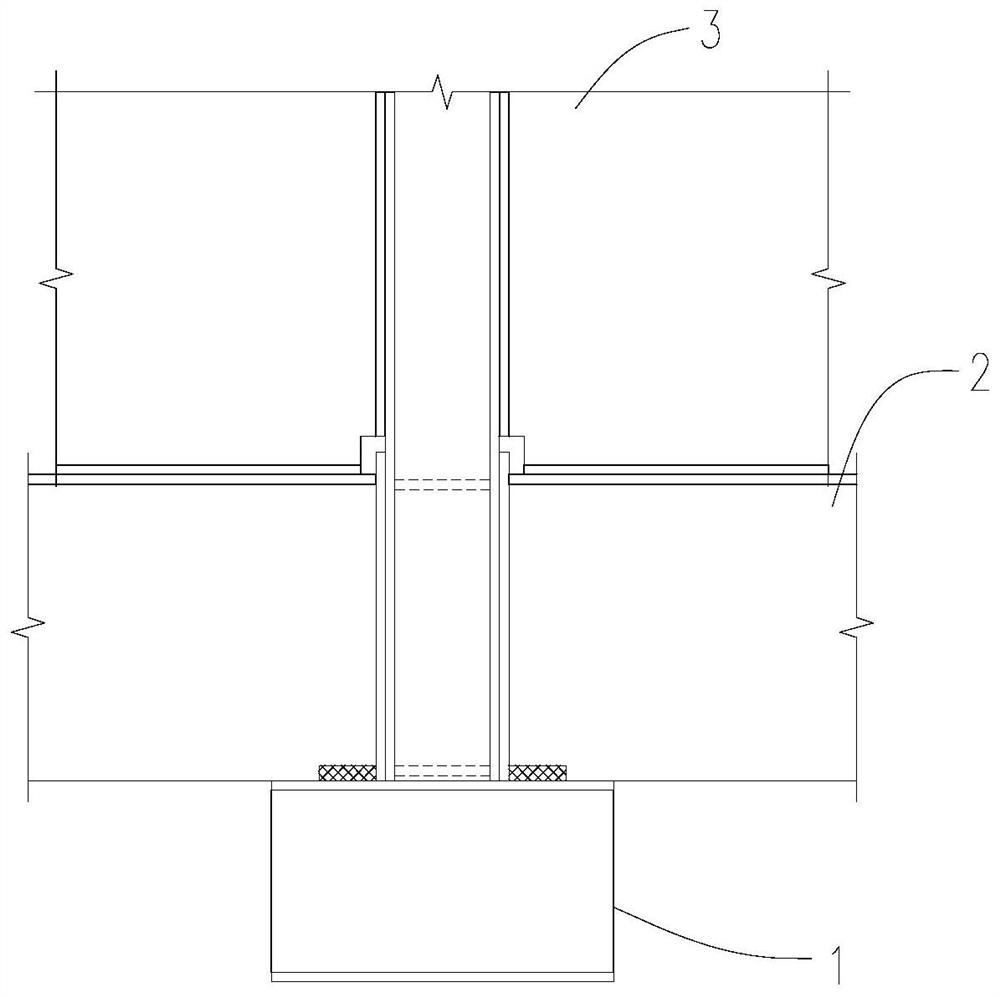
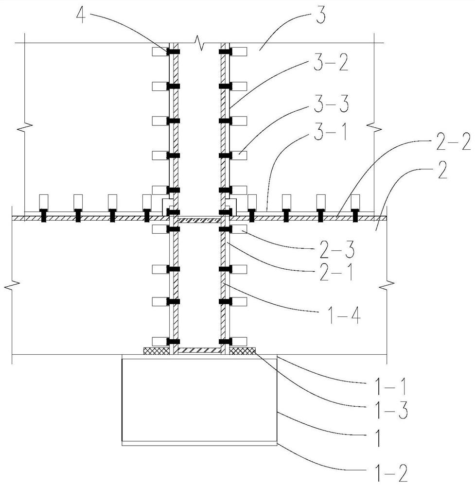
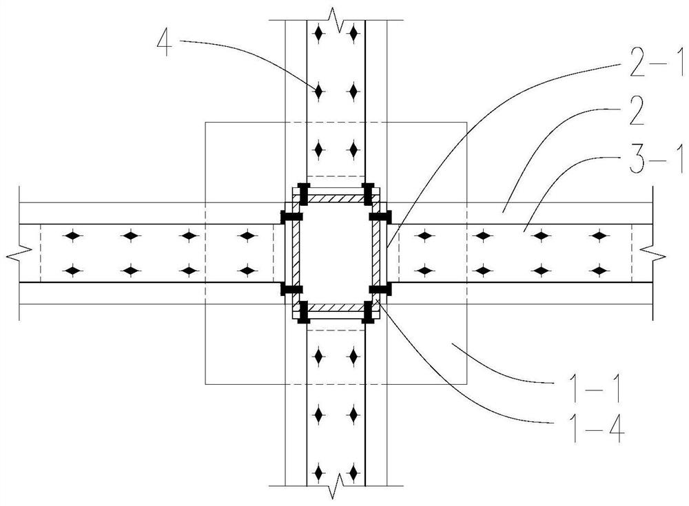
[0030] Such as figure 1 As shown, it is the prefabricated concrete ground beam-shear wall connection node according to the present invention, which includes a conversion column 1 , a ground beam 2 and a shear wall 3 .

[0031] The bottom and top of the conversion column 1 are pre-embedded with the top steel plate 11 and the bottom steel plate 12 respectively with bolt holes, and the inner longitudinal ribs of the conversion column 1 are welded to the pre-embedded top steel plate 11 and bottom steel plate 12 at the upper and lower ends; the conversion column 1 The upper part is provided with a stem 14, the bottom of the stem 14 is located inside the conversion column 1, and is integrally connected with the conversion column 1. The stem 14 is made of a rectangular steel pipe, and the four walls are provided with bolt holes. The height of the stem is equal to the height o...


PUM


Abstract

The invention discloses a prefabricated concrete ground beam-shear wall connecting joint and a construction method thereof. The prefabricated concrete ground beam-shear wall connecting joint comprises a conversion column, a ground beam and a shear wall. A core column is arranged on the conversion column, and the height of the core column is equal to the sum of the heights of the ground beam and the shear wall; a first end steel plate and a top steel plate are correspondingly arranged on the end face and the top face of the ground beam, and a second end steel plate and a bottom steel plate are correspondingly arranged on the end face and the bottom face of the shear wall; and the conversion column, the ground beam and the shear wall are sequentially arranged from bottom to top, the core column is vertically arranged upwards, the end face of the ground beam and the end face of the shear wall are connected with the core column through a first end steel plate and a second end steel plate correspondingly through bolts, and the top face of the ground beam and the bottom face of the shear wall are connected through a top steel plate and a bottom steel plate through bolts. The anchoring effect is achieved no longer depending on secondary concrete solidification, and the assembling efficiency and the connecting quality are greatly improved.

Description

technical field [0001] The invention belongs to the field of civil engineering and prefabricated assembled structures, and relates to a prefabricated concrete ground beam-shear wall connection node and a construction method thereof. Background technique [0002] The connection nodes and construction methods of prefabricated components are the key issues of prefabricated concrete structures, especially the connection nodes of precast concrete ground beams and shear walls, which have a great influence on the green and low-carbon assembly construction and the overall mechanical performance of the structure. [0003] The existing precast concrete ground beams and shear walls mostly use reserved steel bars, which are connected by grouting sleeves and then poured concrete twice to complete the on-site assembly connection. The steel bars transmit internal force through the grouting sleeves or threaded sleeves, and the post-cast concrete and precast Rough interface for working toget...

Claims


Application Information

Patent Timeline
Patent Type & Authority Applications(China)
IPC IPC(8): E04B1/58E04B1/20E04B1/21E04B2/00E04C5/03
CPCE04B1/58E04B1/20E04B1/21E04B1/215E04B2/00E04C5/03E04B2001/5887
Inventor 段留省
Owner CHANGAN UNIV
Why Eureka
Try Eureka