
Accurate mechanical bearing and aerostatic bearing associated shafting

An aerostatic bearing and precision machinery technology, which is applied in the direction of bearing components, shafts and bearings, mechanical equipment, etc., can solve the problems of single function and difficulty in realizing ultra-precision machining in the purification room, and achieve improved rotation accuracy, low friction, and precision high effect

Inactive Publication Date: 2008-07-16
THE 45TH RES INST OF CETC
View PDF0 Cites 8 Cited by
  • Summary
  • Abstract
  • Description
  • Claims
  • Application Information

AI Technical Summary

Problems solved by technology

[0003] The purpose of the present invention is to provide a combined shaft system of precision mechanical bearings and air static pressure bearings, to solve the technical problems that the traditional shaft system used for the intermittent rotary workbench of semiconductor special equipment has a single function and is difficult to realize ultra-precision machining in the purification room

Method used


Image

  • Accurate mechanical bearing and aerostatic bearing associated shafting

Examples


Embodiment Construction

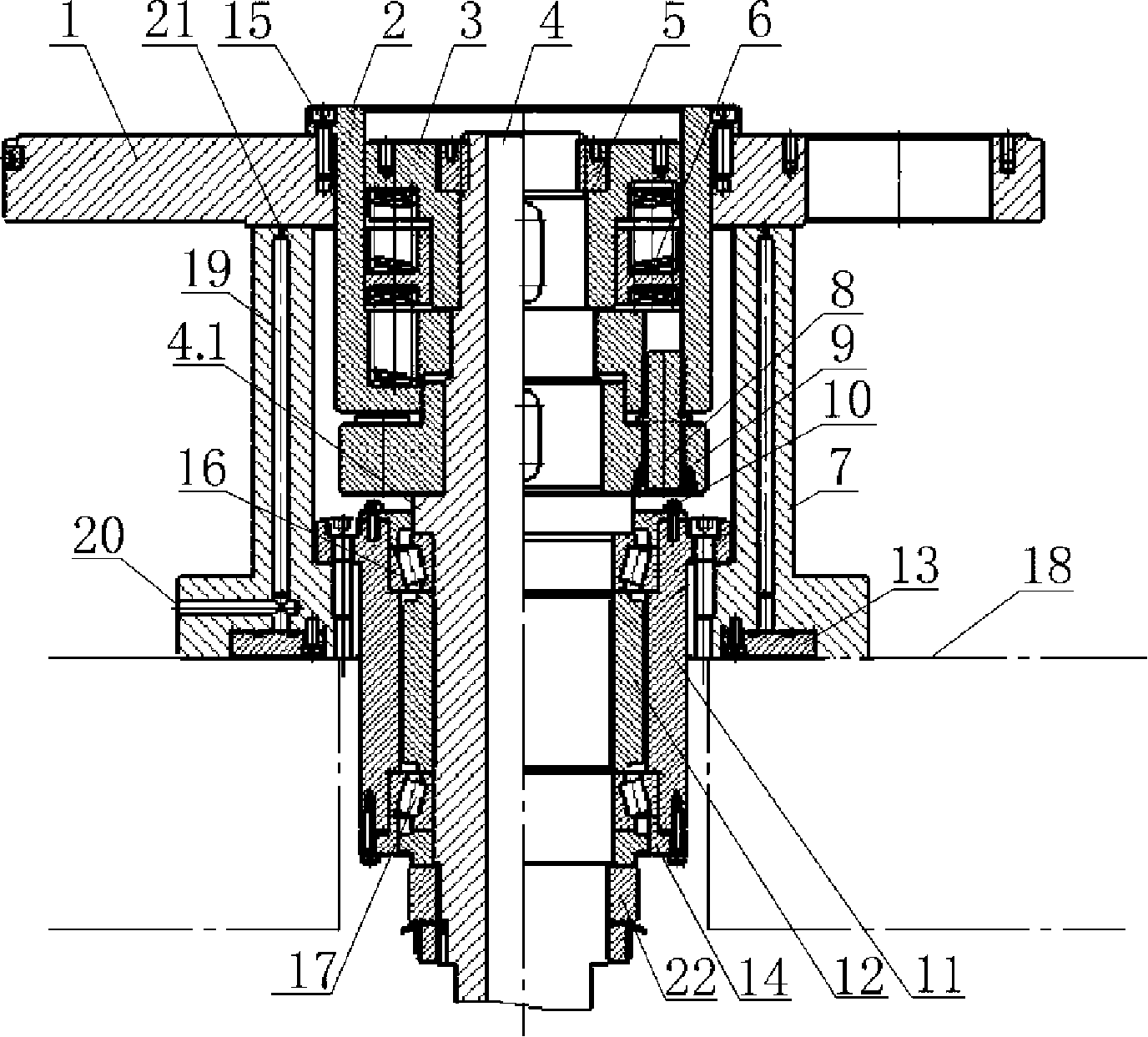
[0019] Examples see figure 1 As shown, this precision mechanical bearing and aerostatic bearing joint shaft system include an upper bearing 16 and a lower bearing 17 connected to the main shaft. The upper bearing 16 and the lower bearing 17 can be precision roller bearings or precision roller bearings. needle bearing. The main shaft 4 is in the shape of a stepped shaft, and there is a ring of flange 4.1 in the middle. There are three steps with gradually smaller diameters from the flange in the middle of the main shaft to the upper end of the main shaft. The transmission disc 9, the connecting sleeve 2 and the adjustment lock are set sequentially from bottom to top. Sleeve 3, transmission disc 9 and connecting sleeve 2 are fixedly connected by pin 8 in the longitudinal direction, connecting sleeve 2 passes through workbench 1, and is fixed with worktable surface by pin 15, and adjusting lock sleeve 3 is connected between main shaft 4 and connecting sleeve 2, the inner ring of...


PUM


Abstract

The invention provides a combined bearing system of a precise mechanical bearing and an air hydrostatic bearing. A mainshaft is a step shaft shape, which is sheathed by a transmission disc, a connecting sleeve and an adjusting lock sleeve sequentially from bottom to top; the transmission disc is connected with the connecting sleeve by a pin; the connecting sleeve is fixed with the surface of a workbench by a pin; the adjusting lock sleeve is a T-shaped ring; the upper section of the adjusting lock sleeve is connected with the mainshaft and the lower section thereof is provided with a spring; an upper bearing, a spacer bush, a lower bearing, a pressing cover and a lower nut are sheathed sequentially from the middle flange of the mainshaft to the lower end; a shaft sleeve is sheathed outside the two bearings; the flange of the mainshaft is sheathed by a sliding sleeve which is fixedly connected with the shaft sleeve; the shaft sleeve is a T-shaped sleeve; the outer convex ring of the shaft sleeve is connected with a cylinder seat; the cylinder wall of the cylinder seat is provided with an axial airway; the air outlet of the airway is distributed on the top surface of the cylinder seat; the lower part of the cylinder seat is fixed with the outer convex ring of the T-shaped shaft sleeve; a sealing ring is embedded on the bottom surface of the cylinder seat; the sealing ring is fixedly connected with the bottom surface of the cylinder seat. The invention is characterized by high precision, high rigidity, low friction, stable operation and being suitable for purification chambers.

Description

(1) Technical field [0001] The invention relates to a connecting shaft system, in particular to a shaft system applied to an intermittent rotary workbench of special equipment for semiconductors. (2) Background technology [0002] The main function of the precision shaft system of the intermittent rotary table of traditional semiconductor special equipment is to accurately transfer the wafer station and provide the necessary rigidity for the table during processing. Therefore, the structural type of the precision shaft system of the worktable has an extremely important influence on the wafer processing quality and processing efficiency. The precision shaft system of the intermittent rotary table used to be a precision mechanical shaft system. Its disadvantages are low precision and poor rigidity, and it can only be used in occasions where the machining accuracy is not high. There is also a traditional method that uses a hydrostatic spindle. This method overcomes the shortco...

Claims


Application Information

Patent Timeline
Patent Type & Authority Applications(China)
IPC IPC(8): F16C35/08H01L21/687H01L21/68
Inventor 王仲康徐旭光
Owner THE 45TH RES INST OF CETC
Learn More