Micro-display electronic division device based on video stacking

A video superimposition and micro-display technology, applied to color TV parts, TV system parts, TVs, etc., can solve the problems of affecting observation and aiming, single information form, etc., and achieve low cost, convenient use, and small size Effect

Inactive Publication Date: 2008-07-16
HENAN COSTAR GRP CO LTD
View PDF0 Cites 6 Cited by
  • Summary
  • Abstract
  • Description
  • Claims
  • Application Information

AI Technical Summary

Problems solved by technology

With the rapid development of modern photoelectric detection technology and network information technology, the requirements for informatization of optical observation equipment are getting higher and higher. It will affect observation and aiming, and the existing video overlay technology can just make up for the shortcomings of traditional reticle devices. How to organically combine the advantages of the two has become a bottleneck for this type of equipment to play a greater role

Method used


Image

  • Micro-display electronic division device based on video stacking

Examples


Embodiment Construction

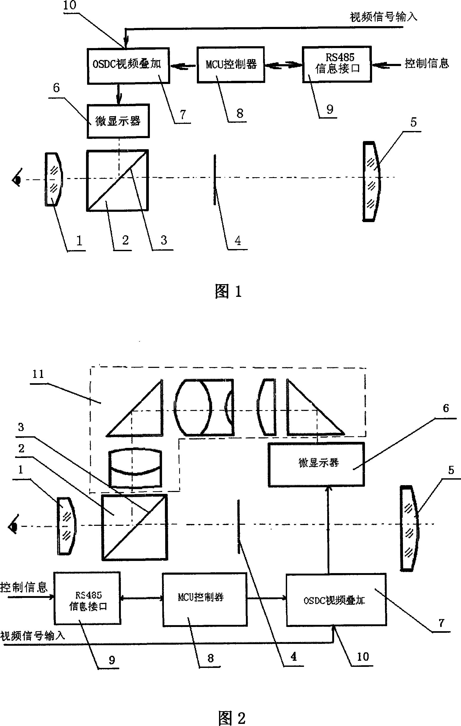
[0012] As shown in Figure 1, the micro-display electronic reticle device based on video superimposition has a main optical path composed of an eyepiece 1 and an objective lens 5, an image plane 4 is arranged between the eyepiece 1 and the objective lens 5, and between the eyepiece 1 and the image plane 4 A beam splitting prism 2 is arranged on the main optical path of the beam splitting prism 2, and a beam splitting film 3 is arranged on the junction surface of the beam splitting prism 2, and a beam splitting path is arranged perpendicular to the main optical path, and the beam splitting prism enters the main optical path through the beam splitting prism 2. The splitting route is composed of an information analyzing unit 9 , a microcontroller 8 , a video superimposing circuit 7 , and a microdisplay 6 . The information analysis unit of the light splitting path is the RS485 information interface, the microcontroller is the MCU controller, the video superimposition circuit is the ...


PUM


Abstract

The invention discloses a micro-display electron graduation device based the overlapping of video which belongs to the video overlapping technology field and is provided with a main optical path consisting of an ocular and a field lens and an image surface is arranged between the ocular and the field lens; wherein, an optical spitting prism is arranged on the optical path between the ocular and an image surface. A joint surface of the optical spitting prism is provided with an optical spitting film and a branch optical path which consists of an information resolving unit, a micro-controller, a video overlapping circuit and a micro-display and is arranged vertical to the main optical path; the image of the micro-display of the branch optical path passes through the images which is projected on the main optical path by the optical spitting prism and the optical spitting film and is conjugated with the image surface of the main optical path. Compared with the prior art, the micro-display electron graduation device has compact and reasonable structure, can overlap images, characters and various special marks in an optical system after synthesizing the images, the characters and various special marks on the video image information, enriches the information types of an optical device maximally and can meet the usages of a piece of optical equipment on each aspect like observation, control, information transfer and measuring, etc.

Description

technical field [0001] The invention belongs to the technical field of video overlay, in particular to a video overlay-based micro-display electronic dividing device combined with photoelectricity. Background technique [0002] The reticle is an indispensable part of optical instruments and equipment, and plays an important role in locating the target during the observation process. Traditional optical instruments use special equipment to score lines on flat glass and fill them with fillers or chemically etch to make reticles. With the rapid development of modern photoelectric detection technology and network information technology, the requirements for informatization of optical observation equipment are getting higher and higher. It will affect observation and aiming, and the existing video overlay technology can just make up for the shortcomings of traditional reticle devices. How to combine the advantages of the two has become a bottleneck for this type of equipment to ...

Claims


Application Information

Patent Timeline
IPC IPC(8): G02B27/00H04N5/265
Inventor 杨亚林曹春青叶挺张瑞闫学纯
Owner HENAN COSTAR GRP CO LTD
Why Eureka
Try Eureka