Plastic rod lens, rod lens array, rod lens plate, image sensor, and printer
A technology of plastic rod and rod lens, applied in the direction of lens, instrument, printing, etc., can solve the problem of no plastic rod lens, etc., and achieve the effect of small chromatic aberration and good color characteristics
- Summary
- Abstract
- Description
- Claims
- Application Information
AI Technical Summary
Problems solved by technology
Method used
Image
Examples
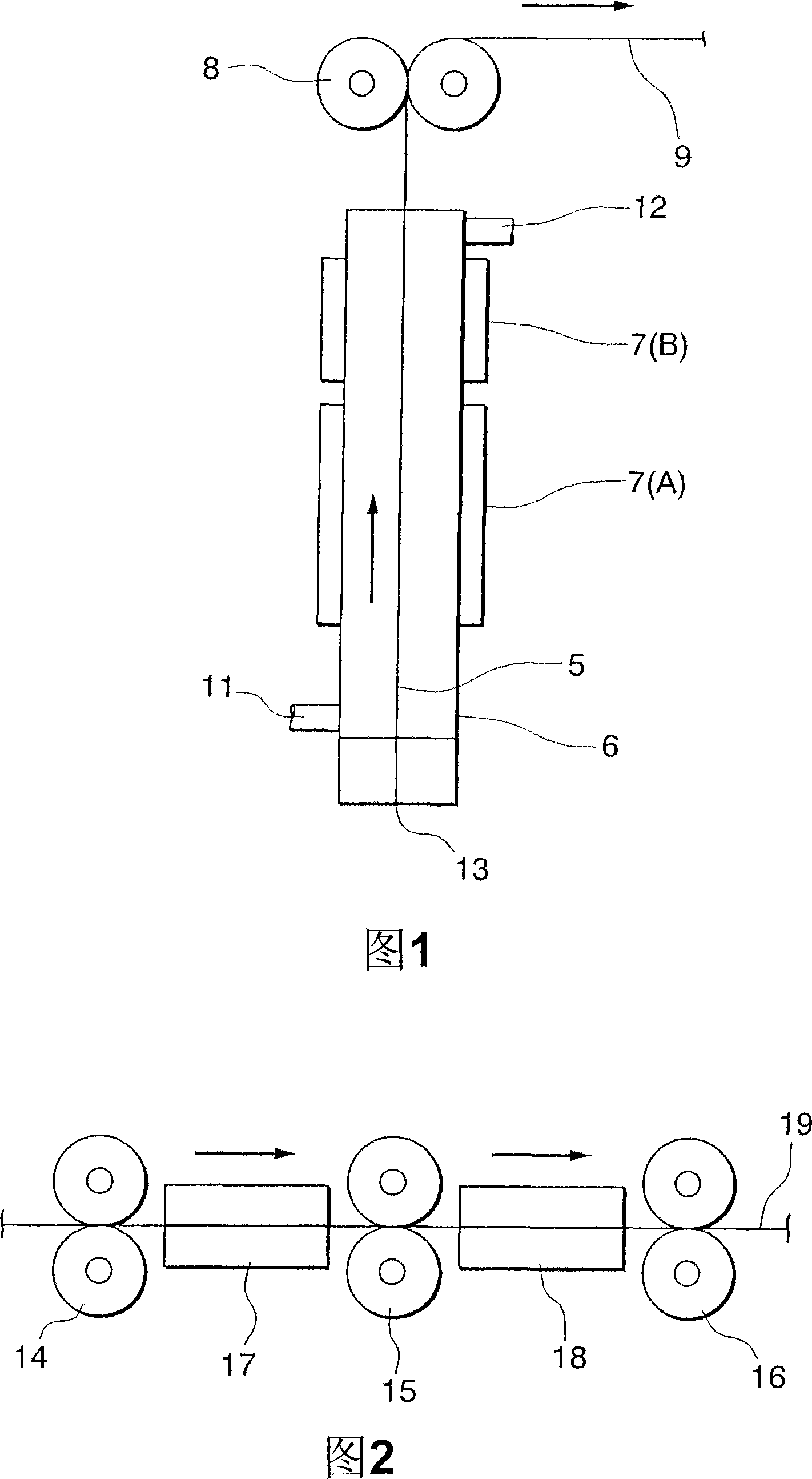
Embodiment 1
[0219] The stock solution of each layer was prepared as shown in Table 2 below.
[0220] Table 2
[0221] Stock composition (mass%)
Physical properties after curing
PMMA
MMA
TDMA
BYZGR
8FM
K
Kmax.-Kmin.
Example 1
Tier 1
46
24
30
-
-
1.502
55.7
166.66
1.90
layer 2
46
29
15
5
5
1.497
54.7
164.76
layer 3
49
37
-
6
8
1.490
54.8
166.64
layer 4
47
23
-
10
20
1.484
54.2
166.18
layer 5
39
3
-
17
41
1.472
53.2
165.91
Comparative example 1
Tier 1
47
23
...
Embodiment 2
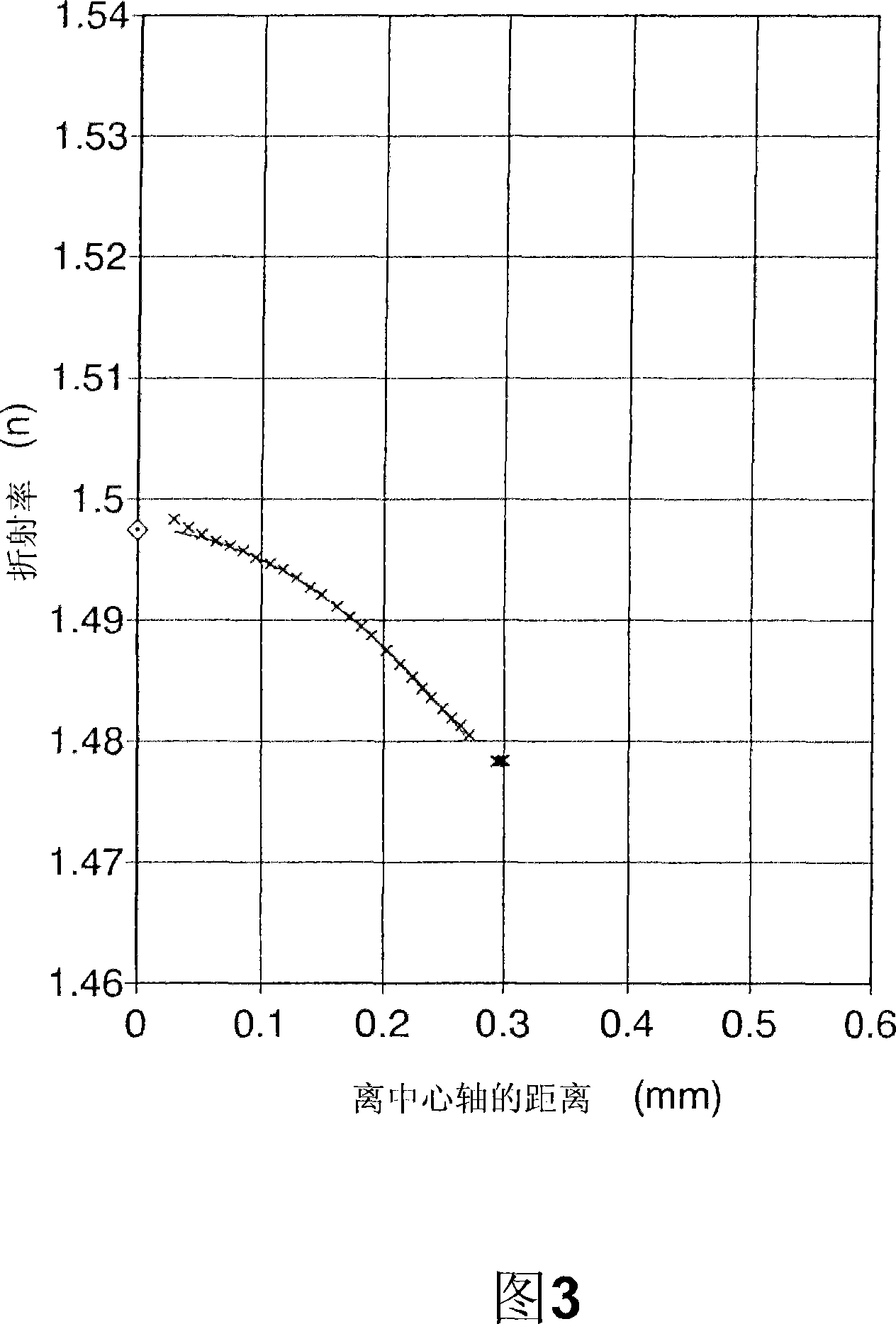
[0247] A plastic rod lens was manufactured in the same manner as in Example 1 except that the draw ratio was changed to 3.50 times and the relaxation rate was changed to 500 / 700.
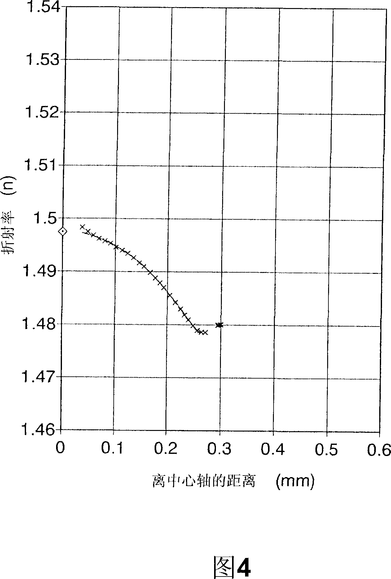
[0248] The radius R of the obtained plastic rod lens is 0.187 mm, and the central refractive index is 1.497. The refractive index distribution in the range of 0.2R to 0.8R from the central axis to the outer periphery is similar to formula (5). In the case of a wavelength of 525nm, the refractive index The distribution constant g is 0.84mm -1 .
[0249] Next, it was the same as in Example 1, except that the distance between the plastic rod lenses was changed from 0.37 mm to 0.39 mm, and the adhesive was changed from "Araldite Rapid" to "s-dine 9607K" manufactured by SEKISUI FULLER Co., Ltd. Fabricated to produce a rod lens array.
[0250] The conjugate length Tc of the rod lens array at 525 nm is 10.0 mm, and the MTF at this time is 72.6%.
[0251] The Tc of the rod lens array was measured at each...
Embodiment 3
[0253] Except having changed the addition amount of the dye of the 4th layer as shown in the following Table 5, it manufactured similarly to Example 2, and manufactured the plastic rod lens and the rod lens array.
[0254] table 5
[0255] dye
Layer 4 (mass%)
Blue ACR
0.003
Blue 4G
0.003
MS Magenta HM-1450
0.003
MS Yellow HD-180
0.006
KAYASORB CY-10
0.003
[0256] The radius R of the obtained plastic rod lens is 0.187 mm, and the central refractive index is 1.497. The refractive index distribution in the range of 0.2R to 0.8R from the central axis to the outer periphery is similar to formula (5). In the case of a wavelength of 525nm, the refractive index The distribution constant g is 0.84mm -1 .
[0257] The conjugate length Tc of the rod lens array is 10.0mm in the case of 525mm, and the MTF at this time is 62.4%.
[0258] The Tc of the rod lens array was measured at each wavelength of 470 nm,...
PUM
| Property | Measurement | Unit |
|---|---|---|
| Radius | aaaaa | aaaaa |
| Radius r | aaaaa | aaaaa |
| Length | aaaaa | aaaaa |
Abstract
Description
Claims
Application Information
 - R&D Engineer
- R&D Manager
- IP Professional
- Industry Leading Data Capabilities
- Powerful AI technology
- Patent DNA Extraction
Browse by: Latest US Patents, China's latest patents, Technical Efficacy Thesaurus, Application Domain, Technology Topic, Popular Technical Reports.
© 2024 PatSnap. All rights reserved.Legal|Privacy policy|Modern Slavery Act Transparency Statement|Sitemap|About US| Contact US: help@patsnap.com


