Spectral optical element, spectral colorimetric apparatus, and image forming apparatus using the same

a colorimetric apparatus and spectral optical element technology, applied in the color field, can solve the problems of insufficient space, several-time detection sensitivity difference between a short-wavelength side and a long-wavelength side in the visible light region, and still remain to be solved, and achieve the effect of small detection color differen

Active Publication Date: 2011-02-03
CANON KK
View PDF8 Cites 22 Cited by
  • Summary
  • Abstract
  • Description
  • Claims
  • Application Information

AI Technical Summary

Benefits of technology

[0015]An object of the present invention is to provide a spectral color sensor in which color mixture caused by high-order diffracted light having a short wavelength is reduced and high-precision spectral information is obtained over the entire evaluation wavelength band in view of optical efficiency of the entire optical system, to obtain small detection color difference relative to chromaticity of a subject to be tested.
[0017]According to the present invention, diffractive efficiency on a short-wavelength side in the evaluation wavelength band of the spectrometer is set to a high value, and hence the generation of second-order diffracted light at a short wavelength may be suppressed to effectively reduce color mixture with first-order diffracted light on a long-wavelength side. Therefore, it is unnecessary to use a high-order diffracted light cut filter, and hence a reduction in cost may be achieved.
[0018]The diffractive efficiency of the first-order diffracted light in the short-wavelength range is improved, and hence a reduction in detection dynamic range at a short wavelength, which is caused by a spectral sensitivity characteristic of a photoelectric conversion element and a spectral transmission characteristic of an illumination optical system, may be compensated. Therefore, higher-precision spectral measurement may be achieved.

Problems solved by technology

The same problem occurs, not only in the electrophotographic type image forming apparatus but also in a general image forming apparatus for forming a color image such as an ink-jet type image forming apparatus.
When the diffraction spectrometer is used, there have been problems that still remain to be solved.
Therefore, for example, there is a problem that a several-time detection sensitivity difference between a short-wavelength side and a long-wavelength side occurs in the visible light region.
A halogen lamp or a xenon lamp, which has conventionally been used, has a problem in terms of necessary space and a problem of heat generation.
Even in an ultraviolet-excitation type white LED of which a color rendering property is said to be high, a spectral intensity in the short-wavelength region is significantly lower than a spectral intensity at the center wavelength, and hence the insufficient sensitivity of the one-dimensional array detector cannot be compensated.
However, a plastic material (polymethylmethacrylate (PMMA) or polycarbonate) generally has a low transmittance in the short-wavelength region, and hence the insufficient sensitivity of the one-dimensional array detector cannot be compensated.
However, high-order undesirable diffracted light is actually generated.
Therefore, there is a problem that a difference occurs between the original chromaticity of the subject to be tested and detected chromaticity.
However, the high-order diffracted light cut filter is expensive, it is essential to reduce a size of the cut filter to be incorporated into an image forming apparatus, and there is another disadvantage in reducing the number of parts for needs to reduce an apparatus size.

Method used


Image

  • Spectral optical element, spectral colorimetric apparatus, and image forming apparatus using the same
  • Spectral optical element, spectral colorimetric apparatus, and image forming apparatus using the same
  • Spectral optical element, spectral colorimetric apparatus, and image forming apparatus using the same

Examples


embodiment 1

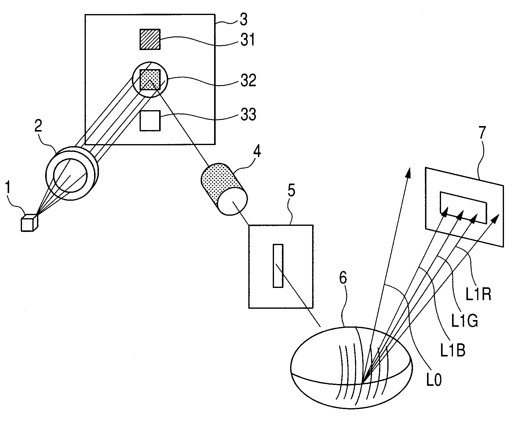
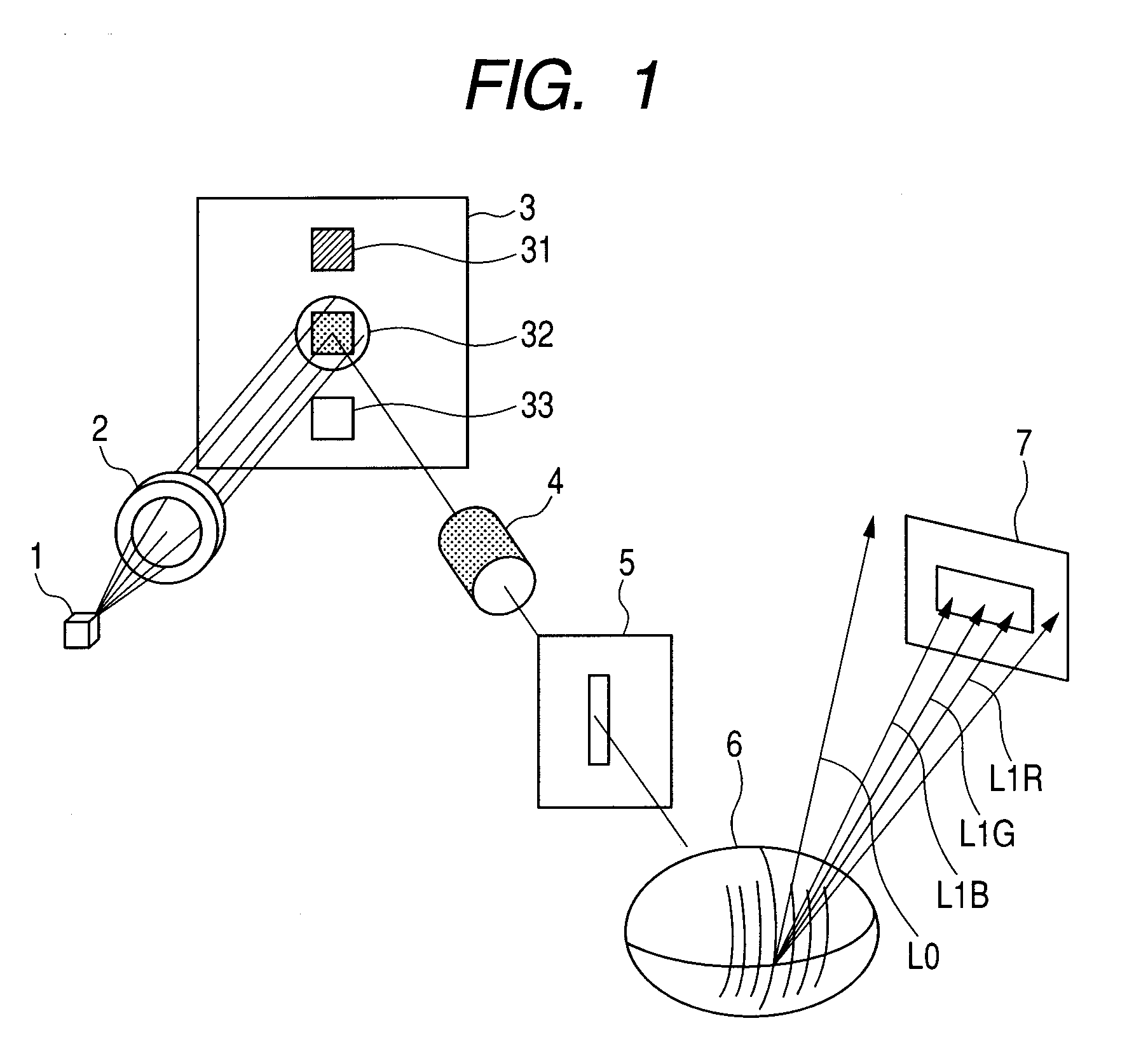
[0039]In this embodiment, an example of a spectral color sensor using a spectral reflection type diffraction optical element according to the present invention is described.

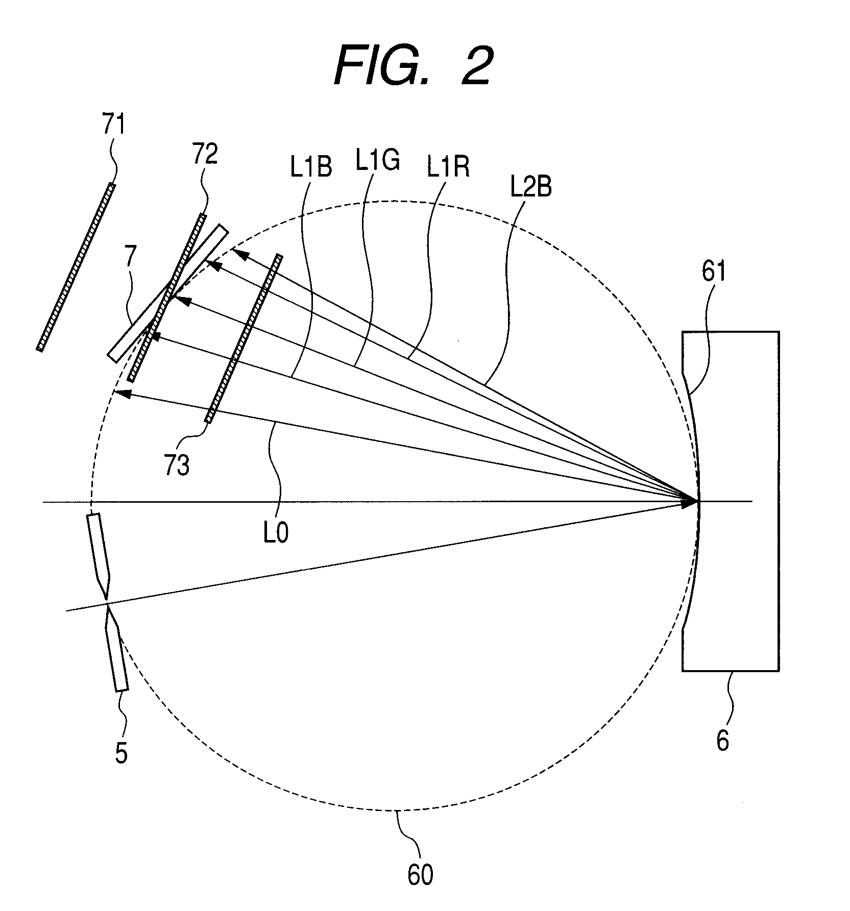
[0040]FIG. 1 is a perspective view illustrating the spectral color sensor using the diffraction optical element according to Embodiment 1 of the present invention. FIG. 2 is a principal cross sectional view illustrating the spectral color sensor. FIG. 3 is a cross sectional view illustrating the diffraction optical element.

[0041]The spectral color sensor of this embodiment has a Rowland type spectrometer structure, which is simple and effective for a reduction in size. When an incident slit 5 and a concave reflection type diffraction optical element 6 are provided on a Rowland circle 60, diffracted light is imaged onto a position on the Rowland circle depending on a wavelength. A one-dimensional array detector 7 is provided on the position, to thereby obtain a spectral intensity distribution at the same time.

[004...

embodiment 2

[0090]Next, a numerical embodiment of a modified embodiment in which the same concave reflection type diffraction optical element 6 as in Embodiment 1 is used is described.

TABLE 3(Spectrometer Specifications)Spectral range400 nm to 700 nmLight sourceUltraviolet LD excitationtype white LEDIncident slit width60 μmIncident slit height2 mmDetection elementSi photo diode arrayDiffraction order m1Pixel pitch of light25 μmreceiving elementSize of light receiving1 mmelement in non-spectraldirectionWavelength resolution3.3 nm

TABLE 4(Diffraction Optical Element Specifications)Base surface meridional line17.5curvature radius (mm)Base surface sagittal line14curvature radius (mm)Grating pitch P (μm)2.52Grating height h (μm)0.200, 0.225Blaze angle θb (°)4.5, 5.1Incident angle α (°)12Reflective filmAl-based multilayer film

[0091]FIG. 9A is a graph illustrating a relationship between the wavelength and the diffractive efficiency D(λ) (=(design order light exit amount) / (incident light amount)) of the...

embodiment 3

Image Forming Apparatus

[0103]FIG. 12 is a principal schematic diagram illustrating a color image forming apparatus according to an embodiment of the present invention. This embodiment illustrates a tandem type color image forming apparatus, in which four optical scanning apparatus are arranged for concurrently recording image information to respective photosensitive drum surfaces each serving as an image bearing member. As illustrated in FIG. 12, a color image forming apparatus 160 includes optical scanning apparatus 11, 12, 13, and 14, photosensitive drums 21, 22, 23, and 24 each serving as the image bearing member, developing assembly 31, 32, 33, and 34, and an intermediate transferring belt 51.

[0104]Respective color signals of red (R), green (G), and blue (B) are input from an external device 52, such as a personal computer, to the color image forming apparatus 160. The color signals are converted into respective image data (dot data) of cyan (C), magenta (M), yellow (Y), and bla...


PUM


Abstract

A concave reflection type diffraction optical element used for a Rowland type spectrometer, in which: the Rowland type spectrometer detects wavelengths in a range including a wavelength λ1 or more and a wavelength λ2 or less (λ1<λ2); the concave reflection type diffraction optical element has a diffractive efficiency D(λ) at a wavelength λ which shows local maximum and maximum value at a wavelength λa satisfying,λ1≦λa<7λ1+3λ210;the concave reflection type diffraction optical element includes a reference surface having an anamorphic shape; and the following condition is satisfied: R>r, where R indicates a meridional line curvature radius of the reference surface and r indicates a sagittal line curvature radius thereof.

Description

BACKGROUND OF THE INVENTION[0001]1. Field of the Invention[0002]The present invention relates to a color sensor using a diffraction grating for color recognition or colorimetry on a subject to be tested, in particular, a color sensor which is suitable for performing colorimetry on toner or printing media in an image forming apparatus.[0003]The present invention may be applied not only to the image forming apparatus but also to a spectral colorimetric apparatus such as a white balance sensor for a digital camera, and other colorimetric apparatus.[0004]2. Description of the Related Art[0005]In an image forming apparatus for forming a color image through an electrophotographic process, a deviation in color tone may occur because of color mixture of toner. The same problem occurs, not only in the electrophotographic type image forming apparatus but also in a general image forming apparatus for forming a color image such as an ink-jet type image forming apparatus.[0006]For example, Japan...

Claims


Application Information

Patent Timeline
Patent Type & Authority Applications(United States)
IPC IPC(8): G01J3/28
CPCG01J3/02G01J3/0218G01J3/024G01J3/10G02B5/1861G01J3/2803G01J3/50G01J3/501G01J2003/468G01J3/20
Inventor TAKIZAWA, TOKUJIKIMURA, KAZUMI
Owner CANON KK
Why Eureka
Try Eureka