Energy-efficient sport device

A technology of moving devices and inlets, which is applied in transportation and packaging, electric vehicles, vehicle energy storage, etc., to achieve the effect of reducing impact and changing fluid distribution

Active Publication Date: 2008-07-23
朱晓义
View PDF0 Cites 14 Cited by
  • Summary
  • Abstract
  • Description
  • Claims
  • Application Information

AI Technical Summary

Problems solved by technology

[0004] In order to overcome the above four kinds of resistance, lift, positive pressure, side pressure, and negative pressure behind the tail, people have designed various streamlined motion devices, but unfortunately, until now, overcoming resistance has become the largest energy consumption, so there are It is necessary to find an effective method that can really reduce resistance

Method used


Image

  • Energy-efficient sport device
  • Energy-efficient sport device
  • Energy-efficient sport device

Examples


Embodiment 1

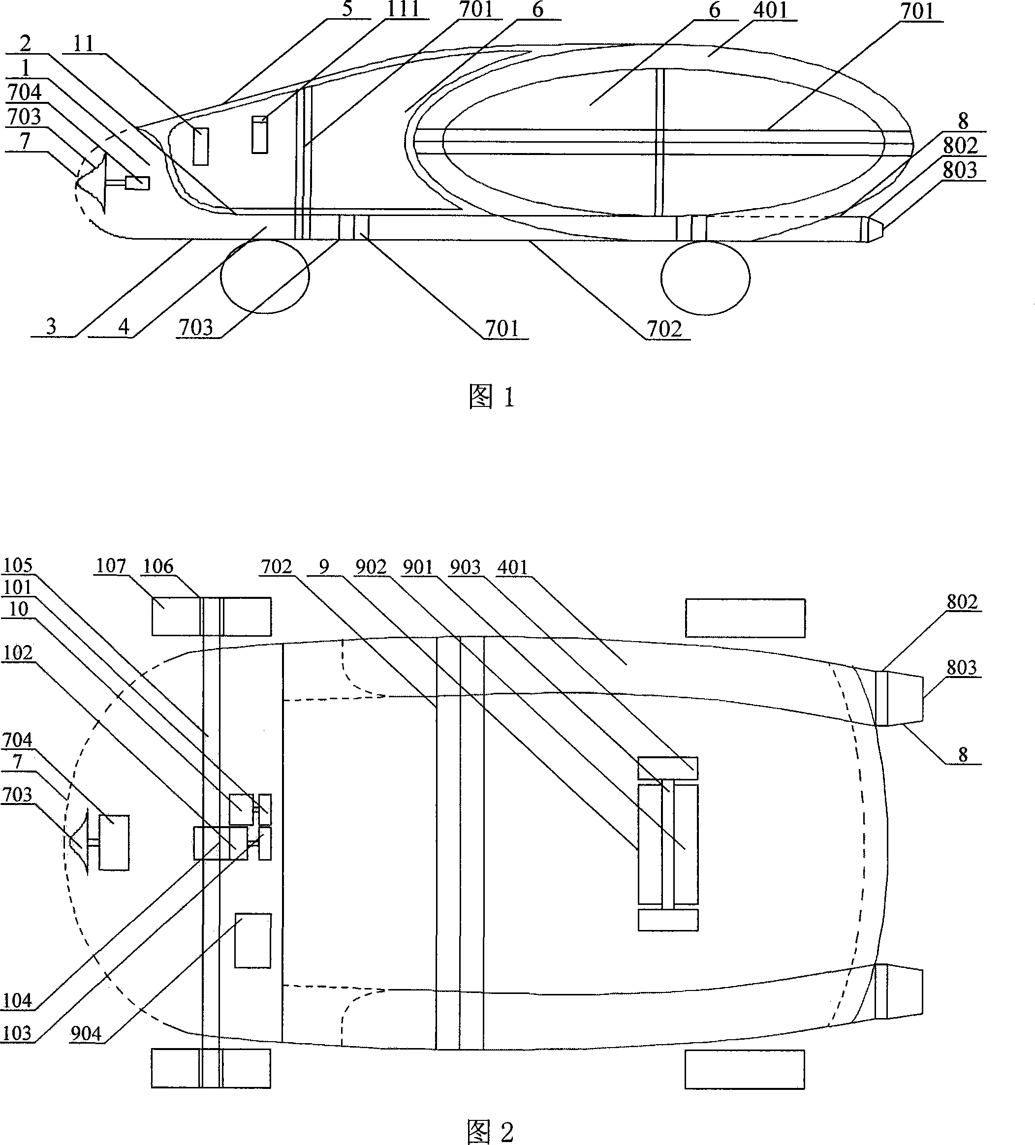
[0028] Embodiment 1, as shown in Figure 1 and Figure 2:

[0029] The front end of the automobile 1 has a fluid inlet 7, which communicates with the fluid layer channel 4 and the two outlets 803 on both sides of the rear. There is a rotating head 703 driven by a motor 704 in the middle of the front-end inlet 7. The shape of the rotating head 703 can be conical, flying saucer-shaped, hemispherical, impeller-shaped, etc., and the rotating head 703 rotates at a high speed. Under the action of centrifugal force, it is convenient for fluid to be introduced into the fluid. In the hole channel 4, on the contact surface between the rotating head 703 and the fluid, there are concave or convex lines to facilitate breaking through the fluid. The fluid layer channel 4 is bent by the channel of metal material to form an elliptical hole as the ring hole 401, and the fluid in the ring hole 401 The outlet 803 is at the lower part of both sides behind the car body, thereby forming the main stru...

Embodiment 2

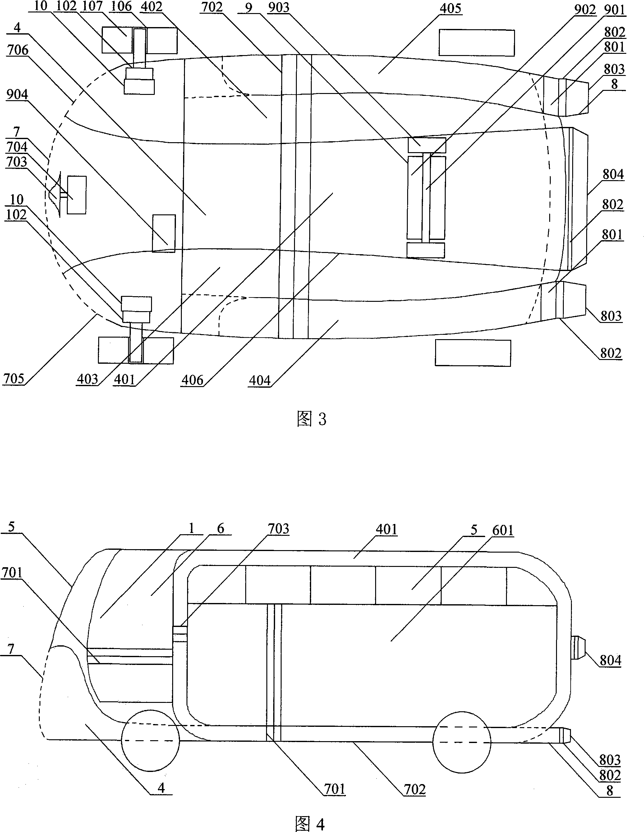
[0035] Embodiment 2, as shown in Figure 1 Figure 3:

[0036] The difference from Example 1 is that there are three front inlets: 7, 706, and 705, which are completely cut off from front to back by two channel plates 406, and are connected to the inlet, the fluid layer channel, the ring channel and the outlet respectively. Three independent channels, that is, the inlets 706, 402, 405, and 803 are connected, 7, 4, 401, and 804 are connected, and 705, 403, 404, and 803 are connected. The fluid layer channel 4 and the channel structure on both sides of the ring hole 401 are metal Material, the middle channel structure is engineering plastics, wherein the wrinkle line 802 on the guide cylinder 8 can bend the upper, middle and lower angles, so that the fluid can be sprayed to the ground or the fluid hole from the desired angle, and the guide cylinder 8 is equipped with a motor 801 capable of absorbing The function of air and blowing, the inlet 706 on the right side of the front end ...

Embodiment 3

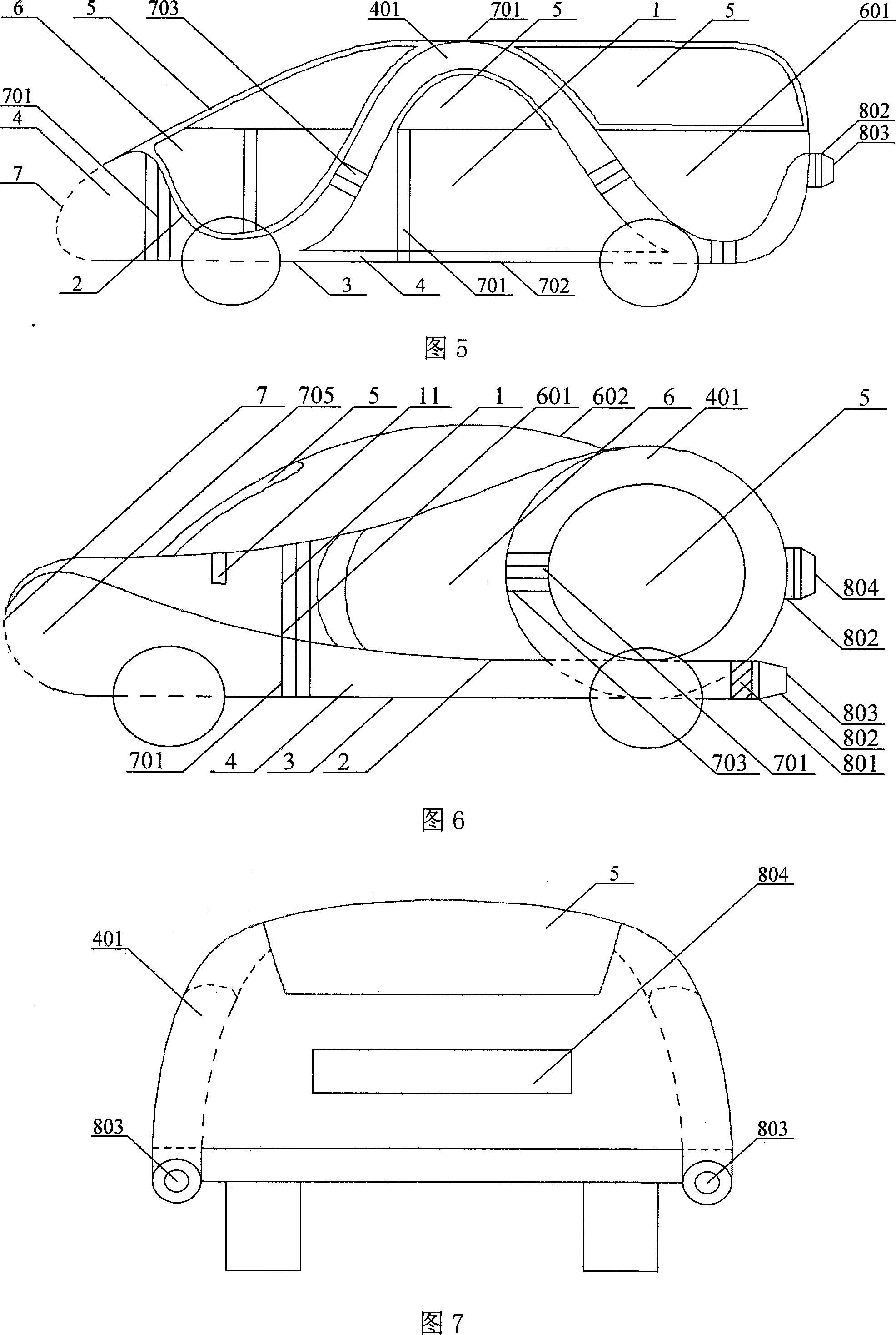
[0038] Embodiment 3, as shown in Figure 4:

[0039] The bus 1 is different from the embodiment 1. Automobile 1 is composed of an inlet 7, a fluid layer channel 4, a ring hole 401 around the automobile shell, a circular outlet 804 in the middle of the rear and two lower outlets 803 on both sides to form the main body of the automobile, and then the front end and the two outlets are installed. The side windshield 5, and the door 6 and the baffle plate 601 are exactly a structure simple and novel and elegant automobile. Wherein the door 6 and the baffle plate 601 are two layers of hollow layers, above which there is an import port 701 to communicate with the ring hole 401, a decorative window 703 is mounted on the import port 701, and the balanced import port 702 at the bottom of the car communicates with the ring hole 401.

[0040] When the automobile 1 is running fast, the fluid wall fluid is introduced into the fluid layer channel 4 from the inlet 7, then passes through the r...


PUM


Abstract

The invention discloses a major structure of an energy-saving motion device which consists of an introduction orifice that has an inner layer and an outer layer, a fluid-layered channel, a loop hole channel, a lead-out orifice channel, and combines with installed windshields, doors and baffles into a car that has novel model and convenient production, and saves cost; an introduction orifice of lateral fluid that is arranged on a car body and a balancing introduction orifice in the bottom of the car are communicated with a channel, a motor is arranged inside the lead-out orifice, a rotating head that is driven by the motor and a wind indicator that is driven by the fluid are arranged in the channel passed by the fluid, thus driving an electric generator to charge a fuel battery for drivingthe motor. The motor, the rotating head, an infinite variable speed controller, a speed reducer, a compensating gear, two semi-shafts and wheels are connected by control boards; the motor drives the wheels to rotate, and eliminates lifting resistance and reduces fluid resistance; the device has enhanced adherence between the wheels and the ground, thus increasing security and stability; the device major structure is formed by channels, thus saving the structures such as pistons, accelerator pedals and so on, and consequently the invention leads the weight to be lighter than the weight of the existing cars by one fourth and saves over two-thirds energy. .

Description

Technical field: [0001] The invention relates to a moving device, in particular to a device moving at high speed in fluid, suitable for trains, automobiles, ships, submarines, airplanes, rockets, missiles and other devices moving in fluid, especially for automobiles. Background technique: [0002] As we all know, since the appearance of automobiles for more than one hundred years, the fluid flow rate at the bottom of the car is slower than that at the upper part of the car. The resulting lift resistance must increase the weight of the lower part of the car chassis. This method reduces energy consumption at the cost of Lift resistance, but until today, lift still causes one of main causes of wasting energy in vain and various traffic accidents. In addition, due to the rapid movement of the car in the fluid, it needs to consume a lot of energy to break through the thick fluid wall in front of the process. After breaking the fluid wall in an instant, the energy of its reaction ...

Claims


Application Information

Patent Timeline
Patent Type & Authority Applications(China)
IPC IPC(8): B60L8/00B62D35/00
CPCY02T10/7083Y02T10/7072Y02T10/82Y02T10/88
Inventor 朱晓义
Owner 朱晓义
Why Eureka
Try Eureka