
Cuneiform honeycomb I-profile component

A wedge-shaped honeycomb and I-beam technology, which is applied to truss-type structures, joists, girders, etc., can solve the problems that the strength of all components cannot be fully utilized, the layout of dense pipelines is complicated, and the average stress level is low, so as to save steel consumption, Reasonable material distribution and large bearing capacity

Inactive Publication Date: 2008-07-23
HARBIN INST OF TECH
View PDF0 Cites 9 Cited by
  • Summary
  • Abstract
  • Description
  • Claims
  • Application Information

AI Technical Summary

Problems solved by technology

[0003] The purpose of the present invention is to solve the problems that the section height of the existing equal-section steel members cannot change with the load, the average stress level is low, and the strength of the whole member cannot be fully exerted, resulting in increased steel consumption and high engineering cost; at the same time In order to solve the problem of complicated layout of dense pipelines due to functional requirements, a wedge-shaped honeycomb I-beam member is provided

Method used


Image

  • Cuneiform honeycomb I-profile component
  • Cuneiform honeycomb I-profile component

Examples


specific Embodiment approach 1

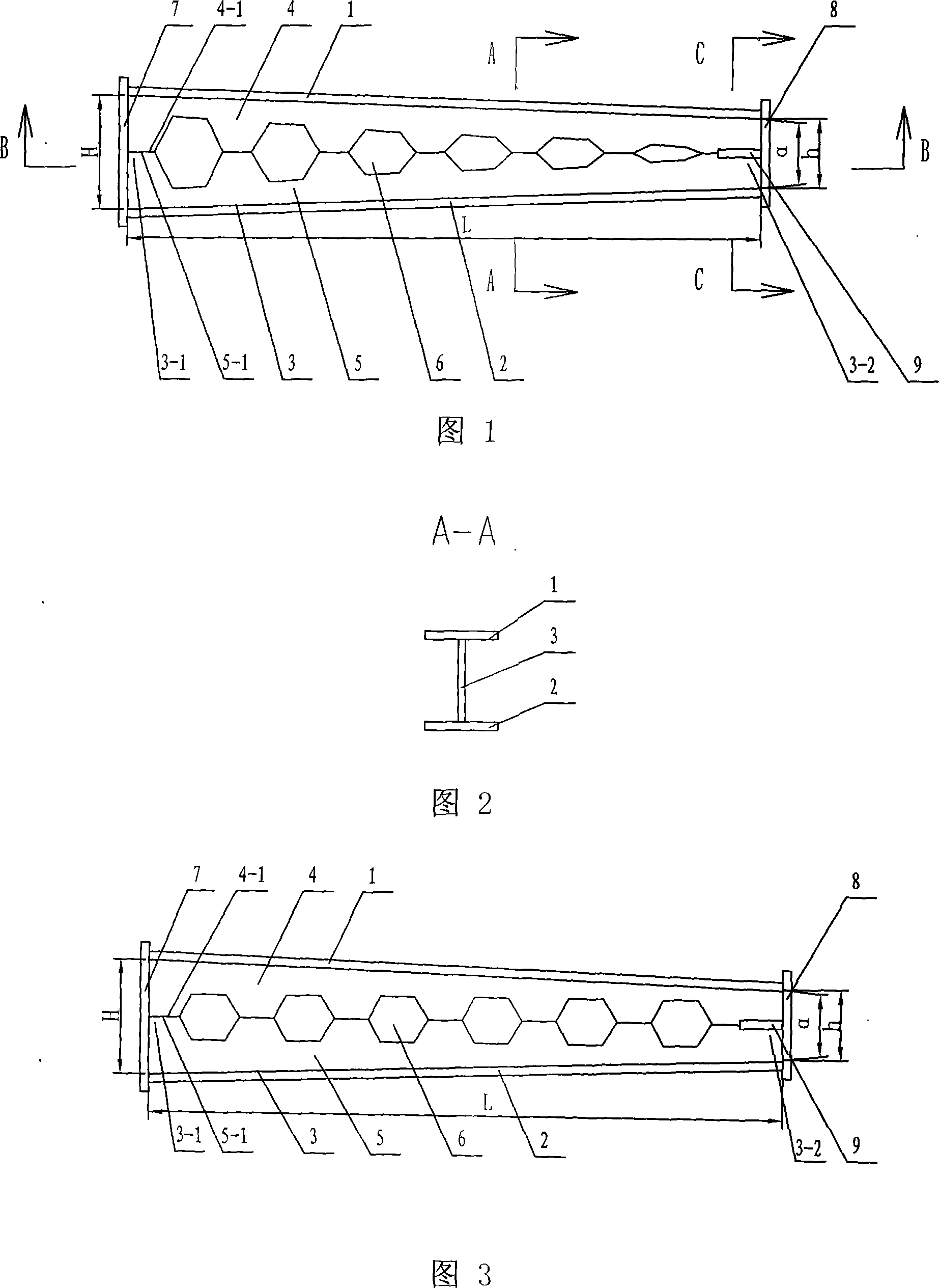
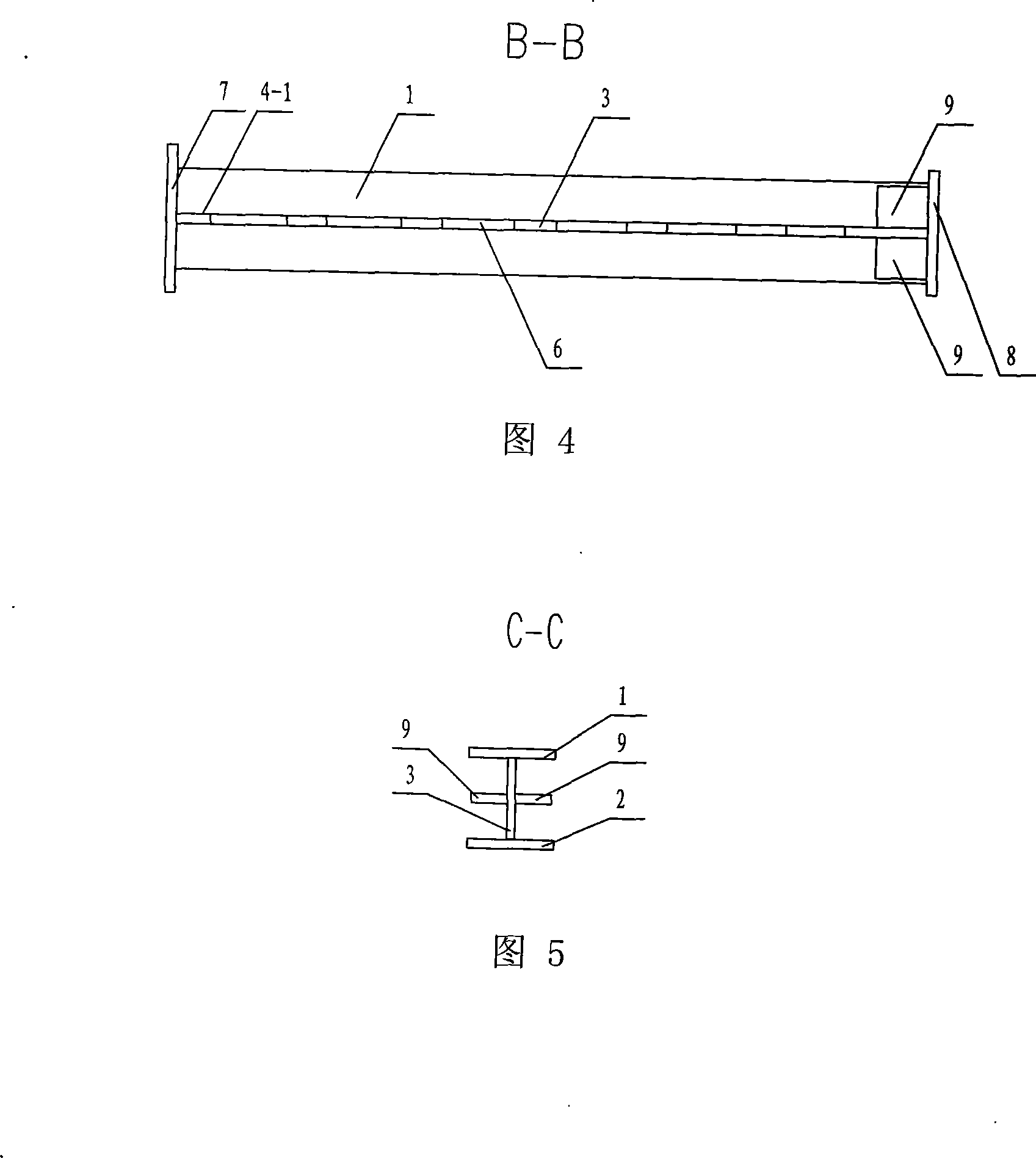
[0007] Specific embodiment 1: This embodiment is described with reference to FIGS. 1 to 3. This embodiment is composed of a section steel upper flange 1, a section steel lower flange 2 and an I-shaped steel web 3. The upper part of the I-shaped steel web 3 is The upper flange 1 of the shaped steel is fixed on the end surface, and the lower flange 2 of the shaped steel is fixed on the lower end surface of the I-shaped steel web 3, and the wedge rate formed by the upper end surface and the lower end surface of the I-shaped steel web 3 is α , the I-shaped steel web 3 is composed of an upper toothed web 4 and a lower toothed web 5, the tooth tip 4-1 of the upper toothed web 4 and the tooth tip 5 of the lower toothed web 5 -1 is fixedly connected, and the tooth tips 4-1 of the upper tooth-shaped web 4 and the tooth tips 5-1 of the lower tooth-shaped web 5 form honeycomb holes 6. The manufacturing method of this embodiment adopts the secondary cutting technology for the prototype st...

specific Embodiment approach 2

[0008] Specific embodiment two: this embodiment is described in conjunction with Fig. 1, the honeycomb hole 6 that the tooth tip 4-1 of the upper tooth-shaped web 4 of this embodiment and the tooth tip 5-1 of lower tooth-shaped web 5 of this embodiment form is from the worker. The hole that becomes smaller successively from the big wedge head 3-1 of the I-beam web 3 to the small wedge 3-2 of the I-beam web 3. The component stress is more reasonable, and the section height change is close to the bending moment diagram under load. Other compositions and connections are the same as in the first embodiment.

specific Embodiment approach 3

[0009] Specific embodiment 3: This embodiment is described in conjunction with FIG. 3 . The difference between this embodiment and specific embodiment 1 is that the tooth tips 4-1 of the upper toothed web 4 and the teeth of the lower toothed web 5 The honeycomb holes 6 formed by the tip 5-1 are holes of equal size. The cutting route is simple and the processing and molding are simple. Other compositions and connections are the same as in the first embodiment.


PUM


Abstract

The invention relates to wedge-shaped honeycomb joist steel member, belonging to the technical field of joist steel members, which solves the problems that the average stress level of the prior constant section type steel member is low; the section height can not change with load action; the whole member intensity can not be brought into full play, which results in the increase of steel consumption and high construction cost; meanwhile the problem of the complex and dense pipeline layout because of the using function requirement is solved. An upper flange (1) of profile steel is fixedly connected with the upper end face of a joist steel web plate (3); a lower flange (2) of profile steel is fixedly connected with the lower end face of the joist steel web plate (3); the tapering ratio shaped by the upper end face and the lower end face of the joist steel web plate (3) is Alpha; the joist steel web plate (3) comprises an upper tooth-shaped web plate (4) and the lower tooth-shaped web plate (5); a cusp (4-1) of the upper tooth-shaped web plate (4) is fixedly connected with a cusp (5-1) of the lower tooth-shaped web plate (5); a honeycomb hole (6) is formed by the cusp (4-1) of the upper tooth-shaped web plate (4) and the cusp (5-1) of the lower tooth-shaped web plate (5). The wedge-shaped honeycomb joist steel member provides a practical door-type rigid frame system member for industrial and civil building.

Description

technical field [0001] The invention relates to an I-shaped steel component, which belongs to the technical field of building steel structures. Background technique [0002] At present, the light portal frame system has gradually become the first choice for many industrial and civil building steel structure systems due to its advantages of economy, speed and efficiency. It is a new structural system developed in the field of civil engineering in recent years. However, the section height of the existing constant-section steel beams and columns cannot change with the load, the average stress level is low, and the material strength of the entire component cannot be fully exerted, which leads to problems such as increased steel consumption and high project cost; There is also the problem of complicated layout of dense pipelines. Contents of the invention [0003] The purpose of the present invention is to solve the problems that the section height of the existing equal-sectio...

Claims


Application Information

Patent Timeline
IPC IPC(8): E04C3/08
Inventor 邵永松金路刘洪波张耀春暴伟
Owner HARBIN INST OF TECH
Learn More