Differential arrangement with assembly openings

A differential and assembly technology, which is applied in the field of motor vehicle transmission system, can solve the problems of uneven distribution and imbalance of the mass of the differential frame, reduce the stiffness and strength of the differential frame, and achieve light weight , high rotational stiffness, small size effect

Inactive Publication Date: 2008-07-23
GKN DRIVELINE INT GMBH
View PDF7 Cites 3 Cited by
  • Summary
  • Abstract
  • Description
  • Claims
  • Application Information

AI Technical Summary

Problems solved by technology

Because of the angular position of the third mounting hole, the mass of the differential mount is unevenly distributed, thus creating an unbalanced state
In general, the problem is that the mounting holes and bearing journal holes significantly reduce the stiffness and strength of the differential mount

Method used


Image

  • Differential arrangement with assembly openings
  • Differential arrangement with assembly openings
  • Differential arrangement with assembly openings

Examples


Embodiment Construction

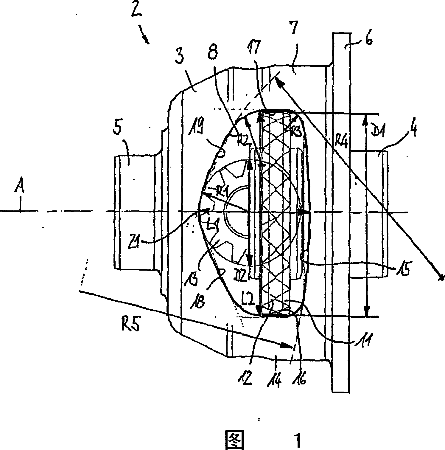
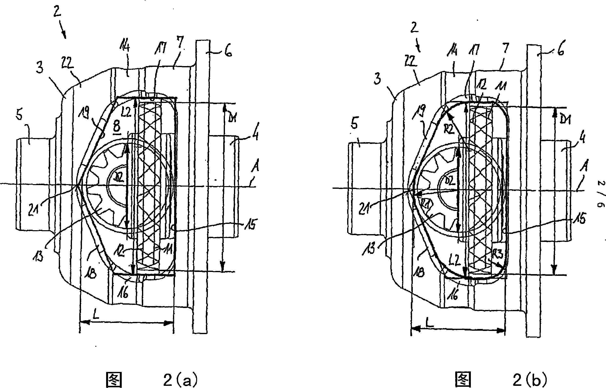
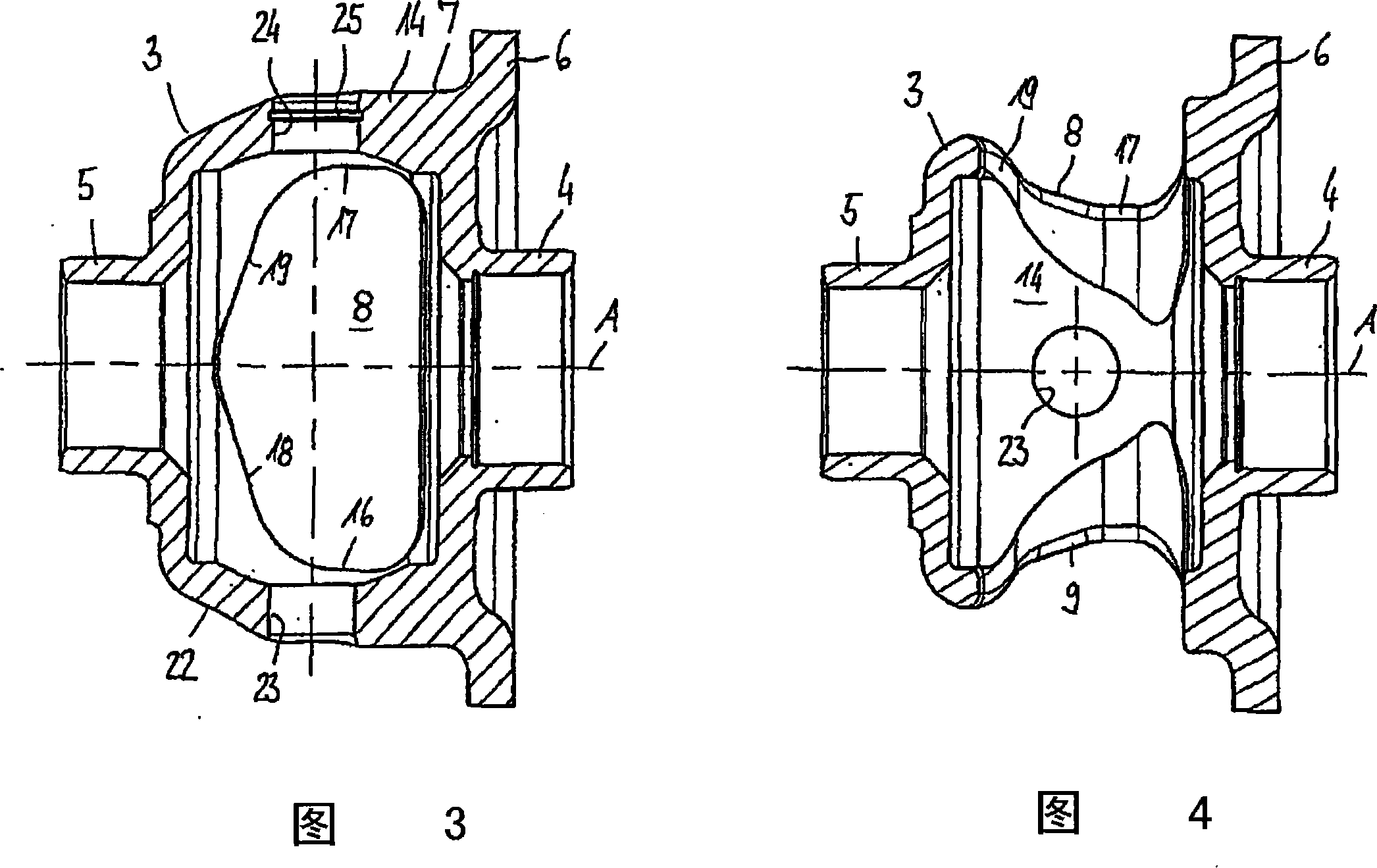
[0030]The differential assemblies 2 shown in FIGS. 1 and 2 substantially correspond to each other in terms of their design and mode of function and will therefore be described jointly below. The same components have the same reference numerals. The figure shows a differential assembly 2 with an integral differential carrier 3, which has to be supported in a fixed housing (not shown). For this purpose, the differential carrier 3 is provided with sleeve-shaped bearing projections 4 , 5 formed thereon, which serve to receive rolling contact bearings (not shown). The differential assembly 2 forms part of a differential transmission in the drive train of a motor vehicle and is used to transmit torque from a propeller shaft (not shown) to the two side shafts. For this purpose, the differential carrier 3 is provided with a flange 6 formed thereon, to which a ring gear can be fixed in order to introduce torque into the differential assembly 2 .

[0031] The one-piece differential ca...


PUM


Abstract

A differential assembly is described, in the form of a crown differential for use in a driveline of a motor vehicle. The differential assembly comprises a one-piece differential carrier which is rotatably drivable around an axis of rotation and, in a casing portion, comprises no more than two identical openings for mounting sideshaft gears rotatably held in the differential carrier on the axis of rotation, as well as differential gears, which rotate jointly with the differential carrier around the axis of rotation and engage the teeth of the sideshaft gears. With reference to a longitudinal central plane, the openings are arranged so as to be mirror-symmetrical and comprise an axial length corresponding at least to the diameter of the differential gears, and a greatest circumferential extension which, in a radial view, corresponds at least to the diameter of the sideshaft gears.

Description

technical field [0001] The present invention relates to a differential assembly forming part of a differential transmission, more particularly a transmission system for a motor vehicle. Such differential assemblies are well known. They typically include a differential carrier rotatably driven about an axis of rotation, two sideshaft gears rotatably held within the differential carrier and used to transmit torque to the two sideshafts, and a plurality of differential carriers. The differential gears rotate jointly within the differential carrier and their teeth mesh with the teeth of the sideshaft gears. Background technique [0002] Differential assemblies are known from US 2 865 229, US 5 620 388 and DE 100 09 961 A1, which comprise a one-piece differential carrier with radial holes that For mounting sideshaft gears and differential gears. In any case, the differential assembly is provided as a bevel gear differential, and the differential and sideshaft gears are provide...

Claims


Application Information

Patent Timeline
Patent Type & Authority Applications(China)
IPC IPC(8): F16H48/00F16H48/10
CPCF16H48/06F16H48/08F16H48/40F16H2048/102F16H2048/382
Inventor W·克吕德R·琉斯成B·康斯坦丁
Owner GKN DRIVELINE INT GMBH
Why Eureka
Try Eureka