Machine tool

A technology of machine tools and processing units, which is applied in the field of machine tools, can solve the problems of machining accuracy limitation, positioning accuracy limitation, no disclosure or suggestion, etc., and achieve the effect of reducing machine weight and load

Inactive Publication Date: 2008-07-30
HONDA MOTOR CO LTD
View PDF2 Cites 7 Cited by
  • Summary
  • Abstract
  • Description
  • Claims
  • Application Information

AI Technical Summary

Problems solved by technology

According to such a system, there must be a limit to the degree of accuracy of the positioning, since clearance must be provided between the guide rod and the guide column
In addition, there is a problem that the vibrations induced in the workpiece during the machining operation are easily tra

Method used


Image

  • Machine tool
  • Machine tool
  • Machine tool

Examples


Embodiment Construction

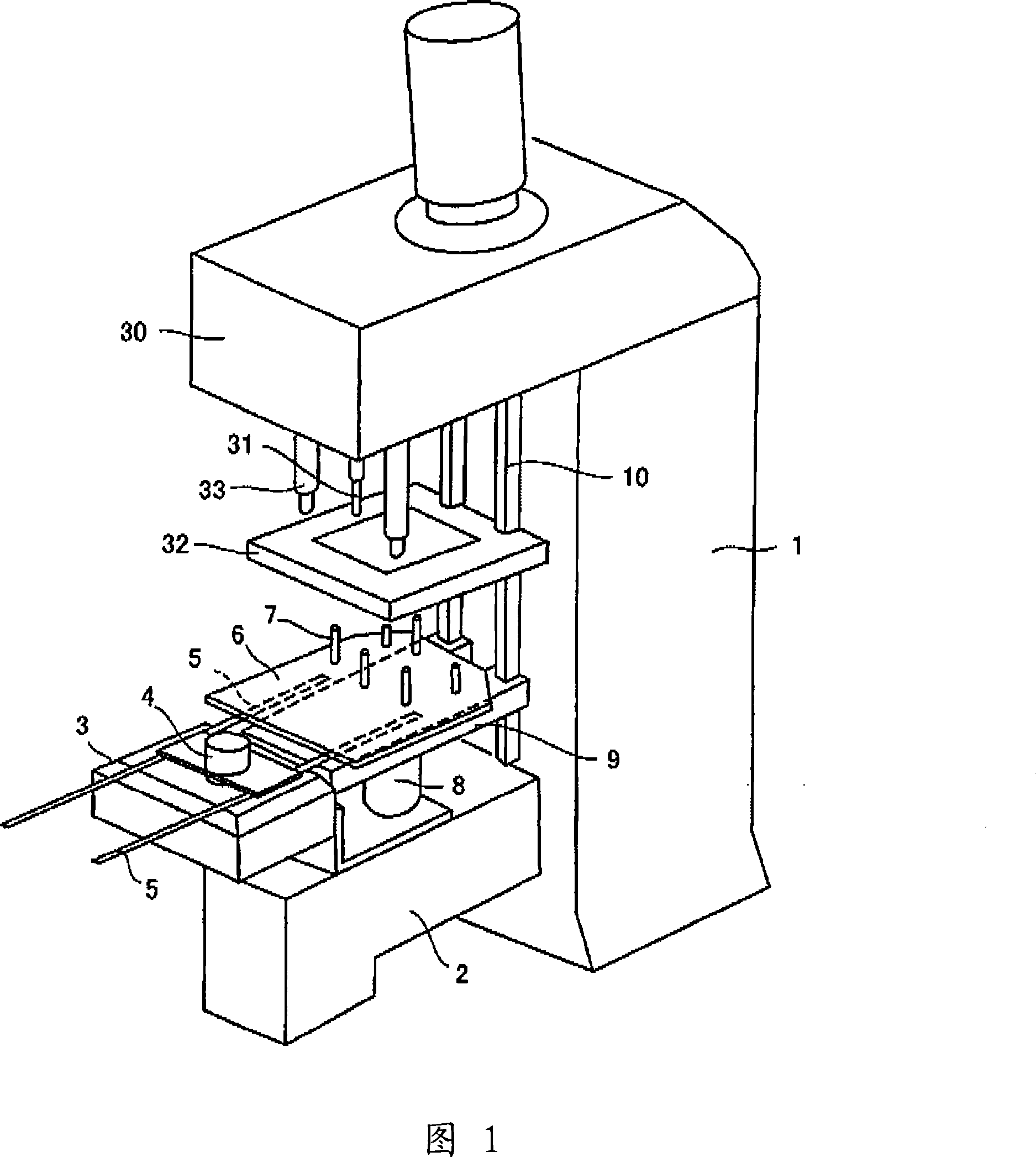
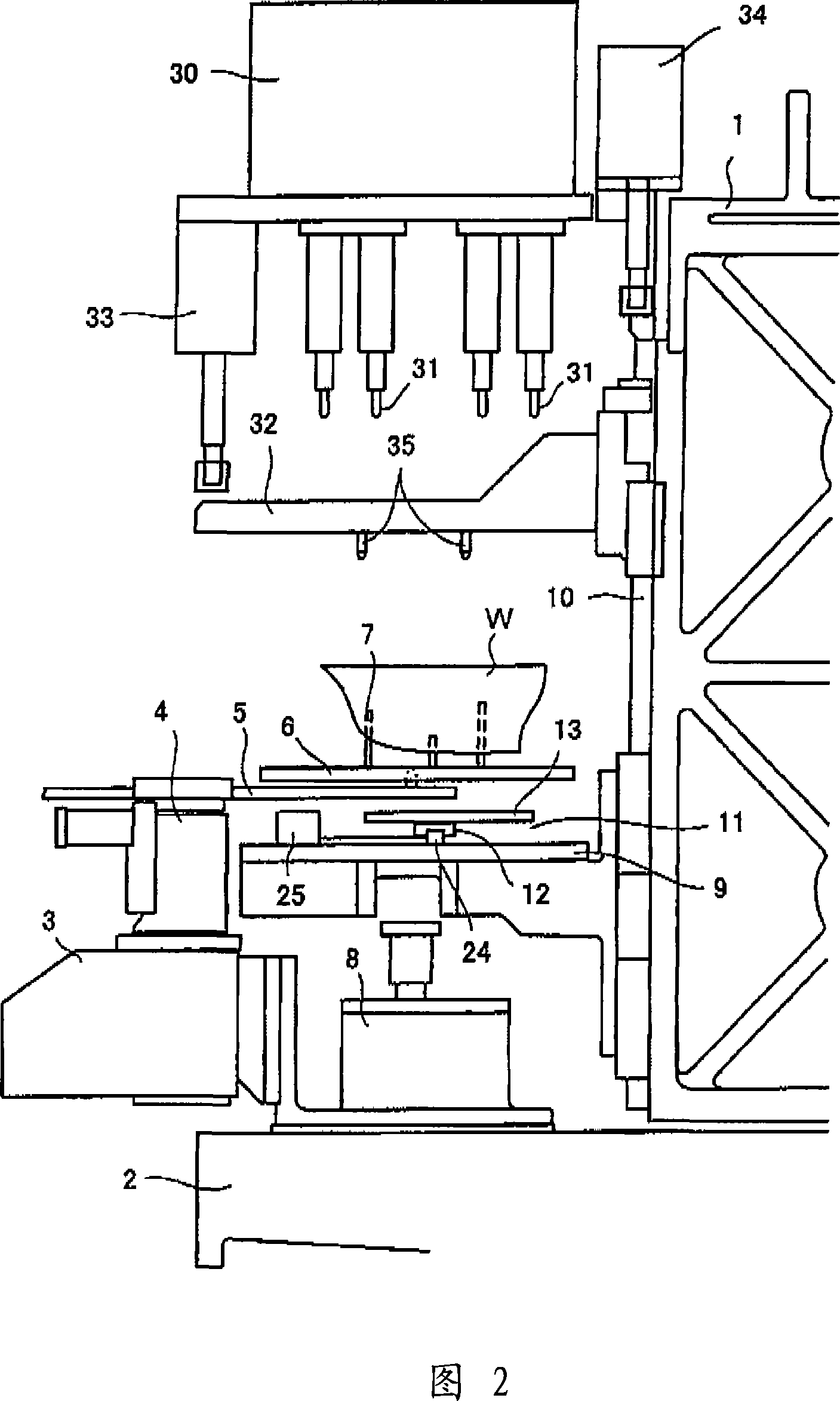
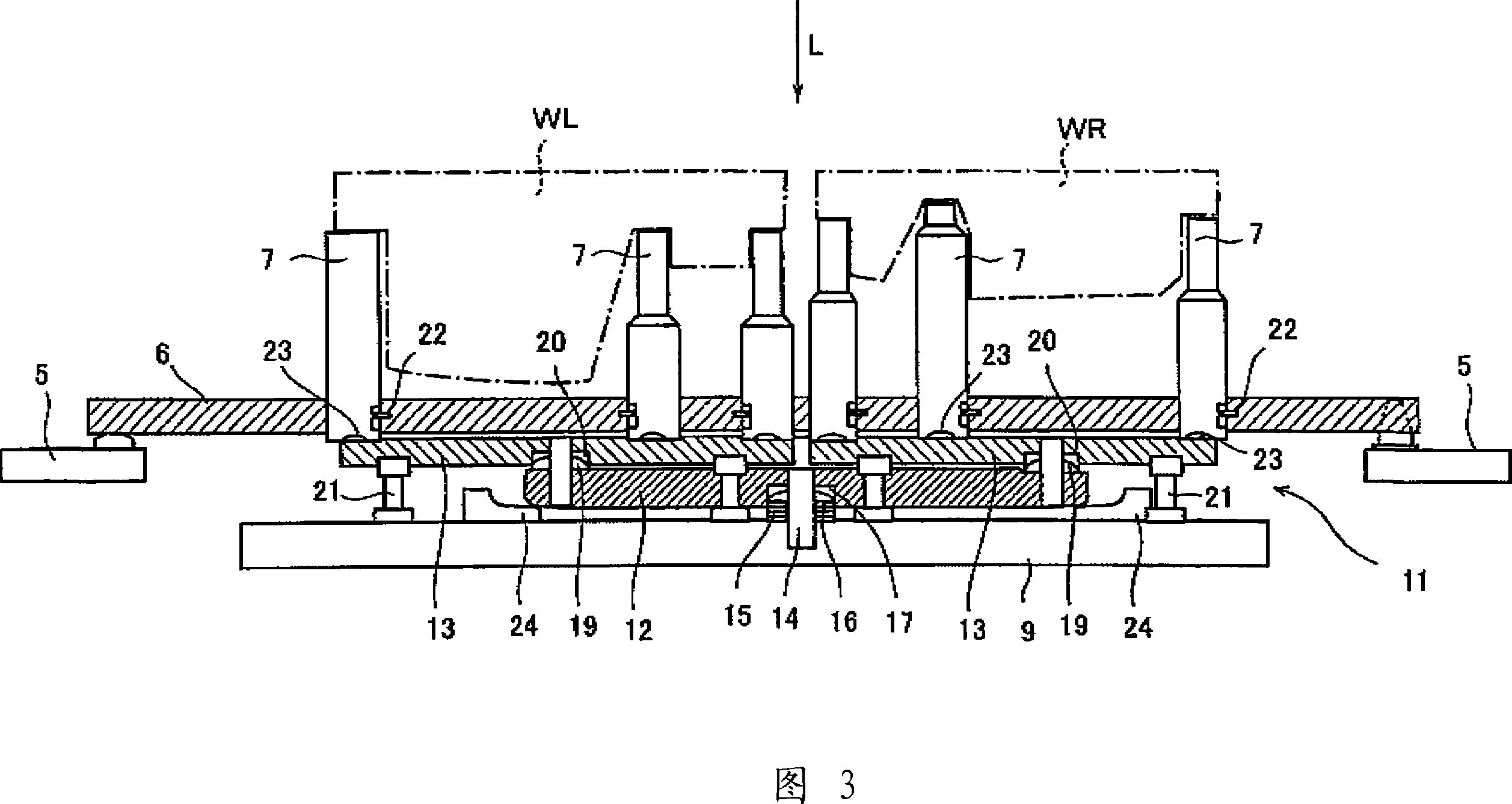
[0030] Illustrative embodiments of the present invention will be explained with reference to the drawings. FIG. 1 is an overall perspective view of a machine tool according to an exemplary embodiment of the present invention. Fig. 2 is a side view of the machine tool in a standby state. Fig. 3 is an enlarged view showing a state where the tray is placed on the bottom plate. Fig. 4 is a front view of the machine tool in a standby state. Fig. 5 is a side view of the machine tool in a processing state. FIG. 6 is a view showing a state where a workpiece is lifted from the position shown in FIG. 5 and then processed.

[0031] In the machine tool, a protruding base portion 2 is provided to a bottom portion of a frame 1 to protrude forward, and a turntable 3 is fitted to an end of the protruding base portion 2 . The respective arms 5, which are out of phase by 180°, are fitted to the shaft 4 of the turntable 3, which shaft 4 is turned by a motor. When the arm 5 is rotated on the...


PUM


Abstract

The invention provides a machine tool with a machining unit (30), a base plate (9) and an intermediate plate (32). The machining unit (30) is fixed to the frame (1). The base plate (9) is movable along rails (10) on the frame (1). The base plate (9) moves the workpiece (W) towards and away from the machining unit (30). The movement of the intermediate plate (32) between the processing unit (30) and the bottom plate (9) along said track (10). The intermediate plate (32) pushes the reference plane of the workpiece (W) provided on the bottom plate (9) in order to position the workpiece (W) in the machining position.

Description

technical field [0001] The invention relates to a machine tool suitable for machining on one side of a reference plane of a workpiece having a reference plane on one surface and no reference plane on the other surface (the surface on the opposite side). Background technique [0002] The gearbox has a right half and a left half. By combining the right and left halves, the gearbox becomes the product. The alignment surface between the right and left halves is used as a reference plane for machining the respective right and left halves. Thus, each half has a reference plane on one surface and no reference plane on the other (opposite) surface. When workpieces with datum planes on only one surface and no datum plane on the other are machined, the datum planes must be precisely positioned relative to the machine axis. [0003] In general, positioning systems are known for assembling guide rods into guide columns when mechanical means relatively position the machine head and th...

Claims


Application Information

Patent Timeline
IPC IPC(8): B23B39/16B23B49/00B23Q3/18
Inventor 三井真吾荒川修吾泉诚
Owner HONDA MOTOR CO LTD
Why Eureka
Try Eureka