Fuel cell system

A fuel cell system and fuel cell stack technology, which is applied in the direction of fuel cell grouping, etc., can solve the problems of reducing the freedom of layout design and storage, and achieve the effect of improving the degree of freedom.

Active Publication Date: 2010-06-16
HONDA MOTOR CO LTD
View PDF5 Cites 0 Cited by
  • Summary
  • Abstract
  • Description
  • Claims
  • Application Information

AI Technical Summary

Problems solved by technology

For this reason, in particular, it cannot be accommodated in a small space for vehicle use, and the degree of freedom in layout design is also reduced.

Method used


Image

  • Fuel cell system
  • Fuel cell system
  • Fuel cell system

Examples


Embodiment Construction

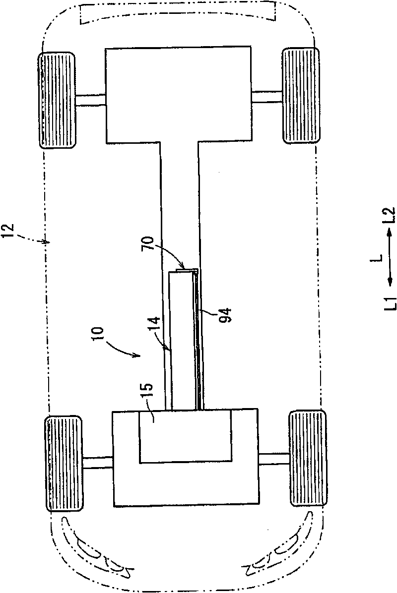
[0023] figure 1 It is an explanatory plan view of a part of a vehicle 12 equipped with the fuel cell system 10 according to the first embodiment of the present invention.

[0024] The fuel cell system 10 includes a fuel cell stack 14 that is arranged at a substantially central portion of the vehicle 12 in the vehicle length direction (arrow L direction). In front of the fuel cell stack 14 in the running direction (direction of arrow L1 ), a device 15 including a contactor and the like for ON / OFF controlling the supply of generated power to the fuel cell stack 14 is arranged.

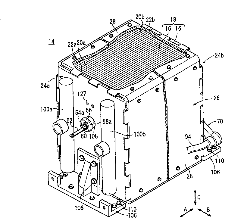
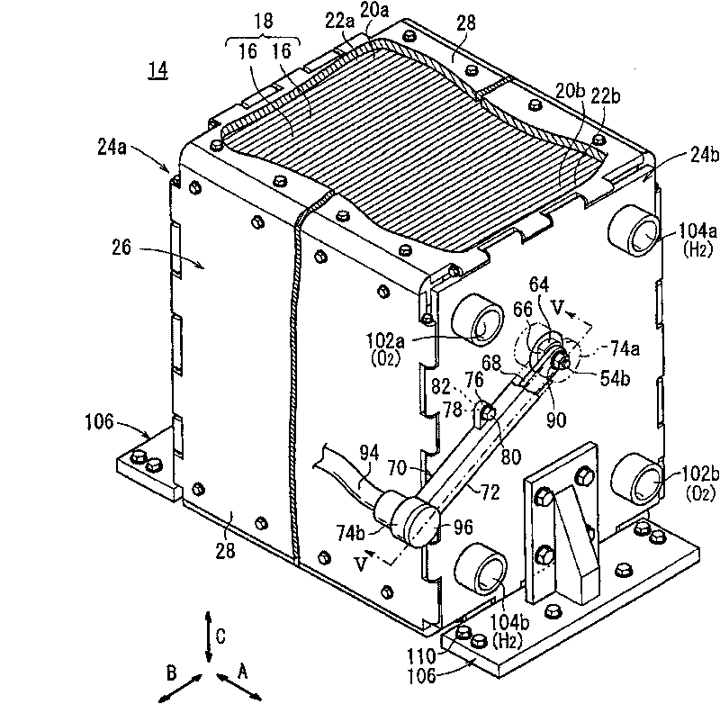
[0025] Such as figure 2 As shown, the fuel cell stack 14 is provided with a stack 18 in which a plurality of power generating elements 16 are stacked in the horizontal direction (arrow A direction). At one end in the stacking direction (arrow A direction) of the stacked body 18, the terminal plate 20a, the insulating plate 22a, and the end plate 24a are arranged facing outward. At the other end in t...


PUM

PropertyMeasurementUnit
thicknessaaaaaaaaaa

Abstract

A fuel cell stack includes a stack body formed by stacking a plurality of power generation cells. At opposite ends of the stack body in a stacking direction, end plates are provided. A second power collecting terminal protrudes outwardly from the end plate. One end of a bus bar is electrically connected to the second power collecting terminal such that the bus bar extends along an end plate surface intersecting the second power collecting terminal. A high voltage cable is connected to the other end of the bus bar. The high voltage cable is drawn toward the end plate.

Description

technical field [0001] The present invention relates to a fuel cell system provided with a fuel cell stack in which a power generating element is provided, and the power generating element has an electrolyte / electrode structure with a pair of electrodes disposed on both sides of an electrolyte and a separator , and in this fuel cell stack, end plates are arranged at both ends in the stacking direction of the stack on which the plurality of power generating elements are stacked, and power extraction terminals are provided protruding outward from each end plate. Background technique [0002] For example, a solid polymer fuel cell has an electrolyte membrane / electrode structure in which an anode-side electrode and a cathode-side electrode are respectively arranged on both sides of an electrolyte membrane (electrolyte) composed of a polymer ion exchange membrane sandwiched between separators. Body (electrolyte / electrode structure) power generation element. Usually, such a fuel ...

Claims


Application Information

Patent Timeline
Patent Type & Authority Patents(China)
IPC IPC(8): H01M8/24
CPCY02E60/521Y02E60/50
Inventor 水崎君春武下寿晶
Owner HONDA MOTOR CO LTD
Why Eureka
Try Eureka