Refrigeration unit

A refrigeration device and cooling capacity technology, applied in refrigerators, refrigeration and liquefaction, lighting and heating equipment, etc., can solve problems such as consumption and excess energy

Active Publication Date: 2008-07-30
DAIKIN IND LTD
View PDF1 Cites 20 Cited by
  • Summary
  • Abstract
  • Description
  • Claims
  • Application Information

AI Technical Summary

Problems solved by technology

However, in the conventional refrigeration equipment, the compressor is always operat

Method used


Image

  • Refrigeration unit
  • Refrigeration unit
  • Refrigeration unit

Examples


Embodiment Construction

[0063] Embodiments of the present invention will be described in detail below with reference to the drawings.

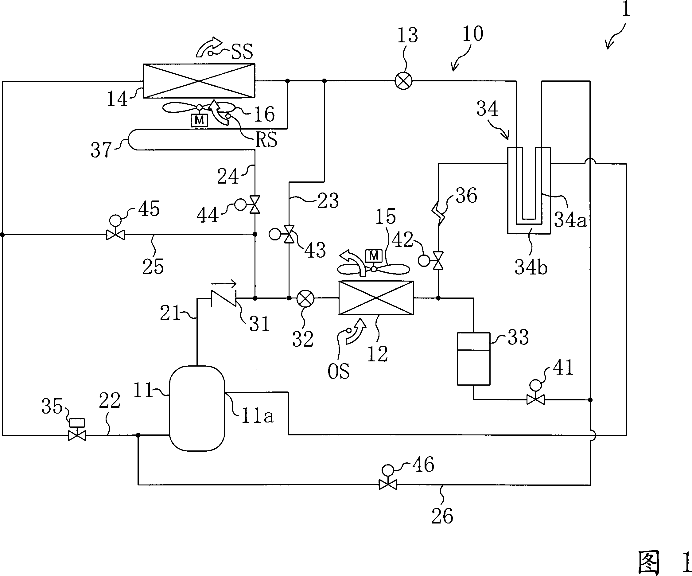
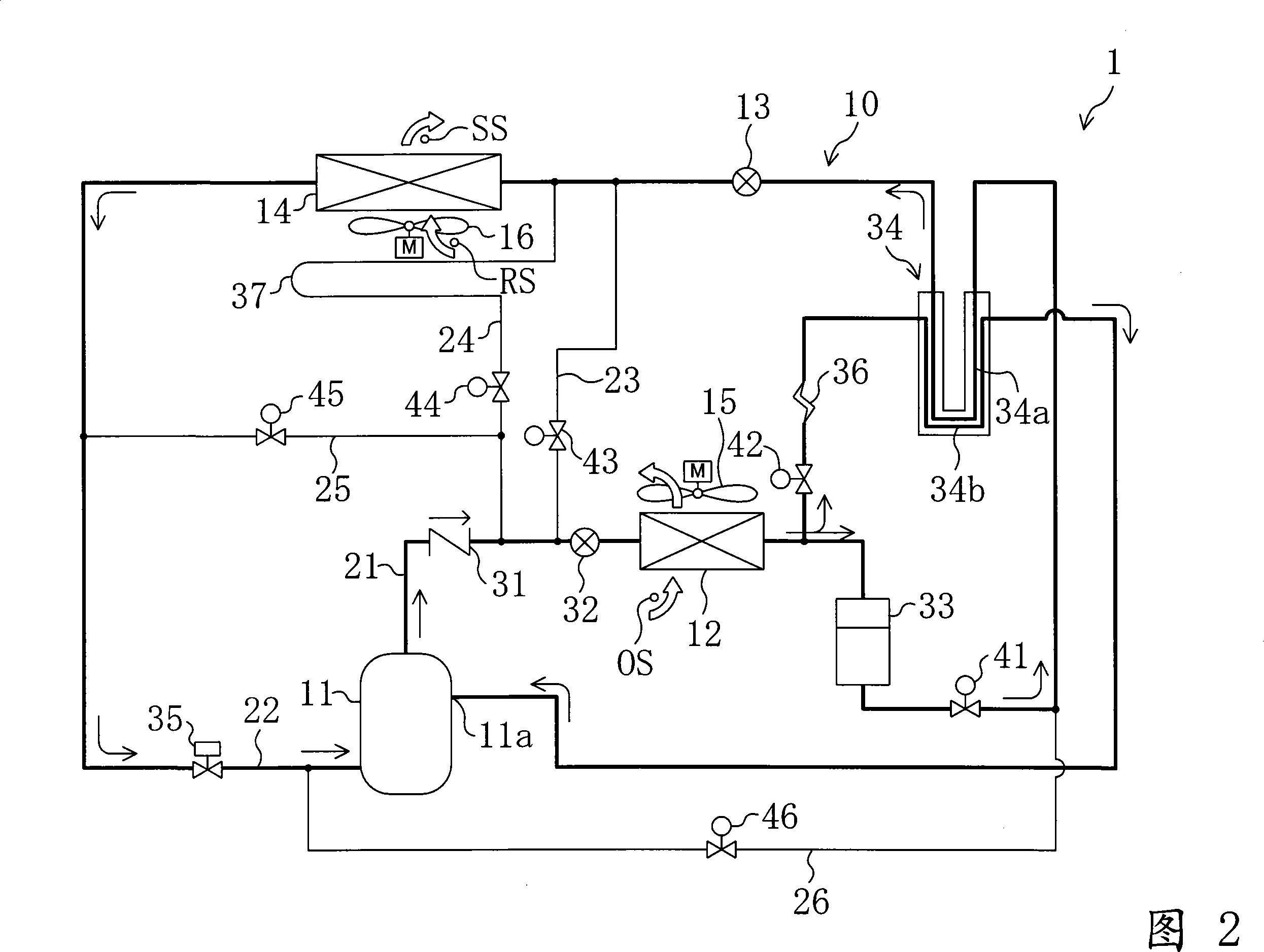
[0064] The refrigerating apparatus 1 of the present embodiment is an apparatus for cooling the inside of a container used for sea transportation or the like. This refrigeration device 1 includes a refrigerant circuit 10 in which a refrigerant is circulated to perform a vapor compression refrigeration cycle.

[0065] In the refrigerant circuit 10 , a compressor 11 , a condenser 12 , an expansion valve 13 , and an evaporator 14 are connected as main components.

[0066] The above-mentioned compressor 11 is constituted by a fixed-capacity scroll compressor whose rotation speed of a compressor motor is constant. The above-mentioned condenser 12 is arranged outside the refrigerator, and constitutes a so-called air-cooled condenser. In the vicinity of the condenser 12, an external fan 15 for sending outside air to the condenser 12 is provided. In addition, heat exchange...


PUM


Abstract

When in the 1 operation the temperature inside is maintained at target temperature by an evaporator, the cooling power of the evaporator is increased so as to carry out the 2 operation for temperature inside lowering. When in the 2 operation the temperature inside reaches lower limit temperature (Tmin), the compressor stops so as to carry out the 3 operation. When in the 3 operation the temperature inside reaches upper limit temperature (Tmax), the compressor restarts so as to carry out the 1 operation.

Description

technical field [0001] The present invention relates to a refrigerating device with a cooling heat exchanger for cooling the inside of a refrigerator, and in particular to an energy-saving operation method of the refrigerating device. Background technique [0002] Conventionally, freezers for cooling the interior of refrigerators, freezers, and the like have been known. [0003] For example, Patent Document 1 discloses a refrigeration device that cools the interior of containers used for marine transportation and the like. The refrigeration unit comprises a refrigerant circuit connected to a compressor, a condenser, an expansion valve and a cooling heat exchanger (evaporator). In the refrigerant circuit of this refrigerating apparatus, a refrigerant is circulated to perform a vapor compression refrigeration cycle. As a result, the refrigerant flowing through the cooling heat exchanger absorbs heat from the interior air and evaporates to cool the interior air. In this refr...

Claims


Application Information

Patent Timeline
IPC IPC(8): F25B1/00
Inventor 田中滋人川胜纪育
Owner DAIKIN IND LTD
Why Eureka
Try Eureka