Steam cylinder head device possessing torsion bar

A cylinder head and torsion bar technology, applied in valve devices, engine components, machines/engines, etc., can solve problems such as valve clearance enlargement, impact on cylinder output effect, and insufficient structural rigidity.

Inactive Publication Date: 2008-08-06
KYMCO
0 Cites 0 Cited by

AI-Extracted Technical Summary

Problems solved by technology

[0010] However, since there is no connecting member between the first and second support walls 22, 23, thermal deformation during operation easily causes deformation and displacement of the first and...

Method used

By the integrated design of the first and second support walls 32 and 33 of the cylinder head 3, and cooperating with the torsion bars 7 connecting the first and second support walls 32 and 33 both sides of the columns 34, the The structural rigidity of the cylinder head 3 is greatly improved, which not only allows the second bearing 51 of the camshaft group 5 to have better concentricity, but also maintains the required rigidity to resist adverse effects caused by thermal deformation . Because of the high rigidity of the structure of the present invention, the gap between the first and second rocker arms 61, 62 and the first and sec...

Abstract

The invention discloses a cylinder head device with a torsion bar, which comprises a cylinder head, a cam shaft group, a swinging arm unit, two space torsion bars and a locking unit, the cylinder head is provided with a cylinder head body, a first supporting wall and a second supporting wall which are spaced and four upright posts which connect two side ends of the first supporting wall and the second supporting wall, a pair of mounting holes which are opposite are formed on the first and the second supporting walls, the swinging arm unit is arranged between the first supporting wall and the second supporting wall, which can swing relative to the cylinder head, the cam shaft group is penetratingly arranged in the two mounting holes, which can drive the swing arm unit to swing, the two torsion bars are upright posts which are bestrid to connect both sides of the first supporting wall and the second supporting wall, and the two torsion bars are locked on the upright post of the cylinder heat through the locking unit. The first supporting wall and the second supporting wall are connected through the two torsion bars, and structure rigidity of the cylinder head is improved to resist imperfect influence which is brought by heat resistance and deformation.

Application Domain

Valve arrangementsMachines/engines

Technology Topic

Rocker armEngineering +4

Image

  • Steam cylinder head device possessing torsion bar
  • Steam cylinder head device possessing torsion bar
  • Steam cylinder head device possessing torsion bar

Examples

  • Experimental program(1)

Example Embodiment

[0020] The foregoing and other technical contents, features and effects of the present invention will be clearly presented in the following detailed description of a preferred embodiment with reference to the drawings.
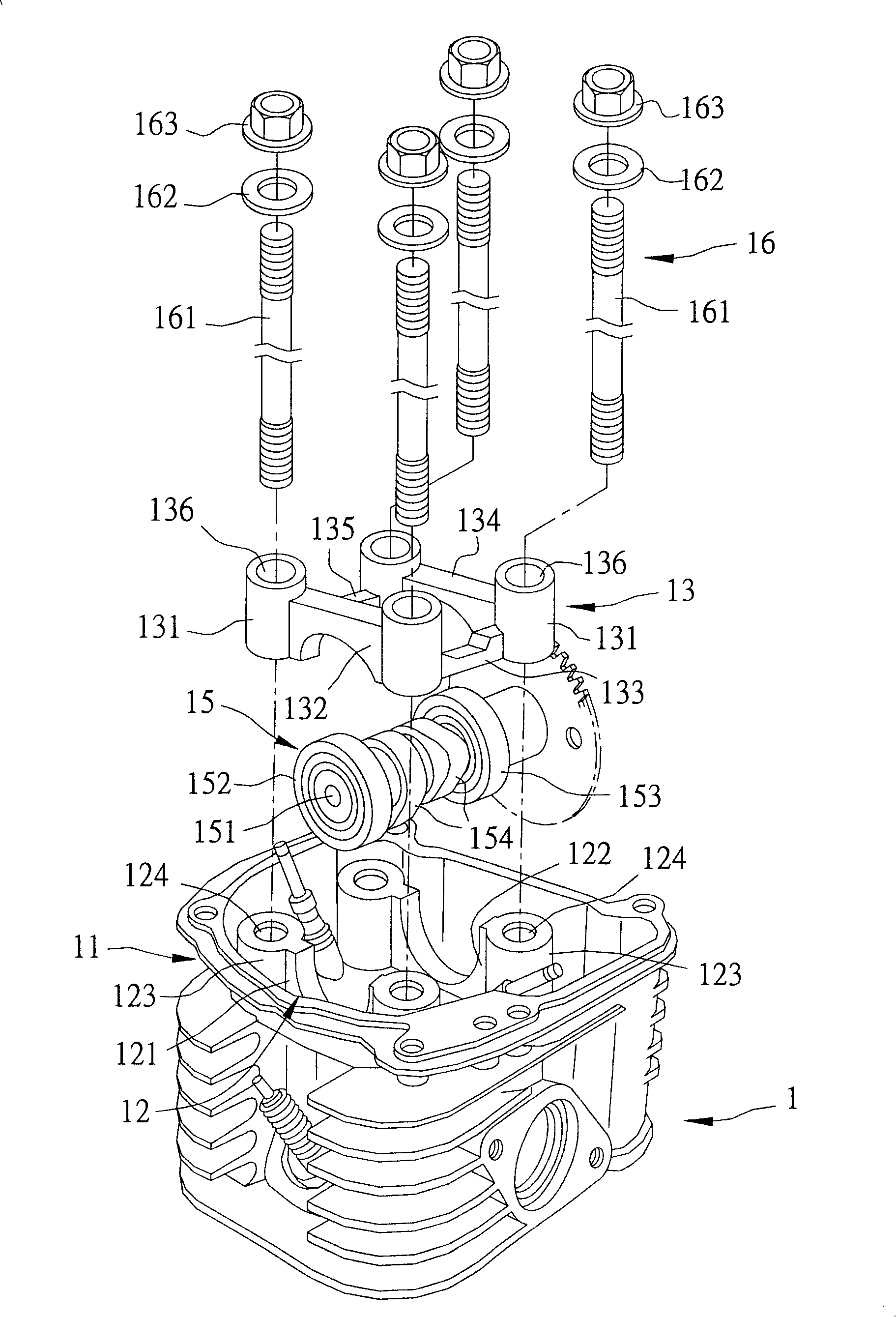
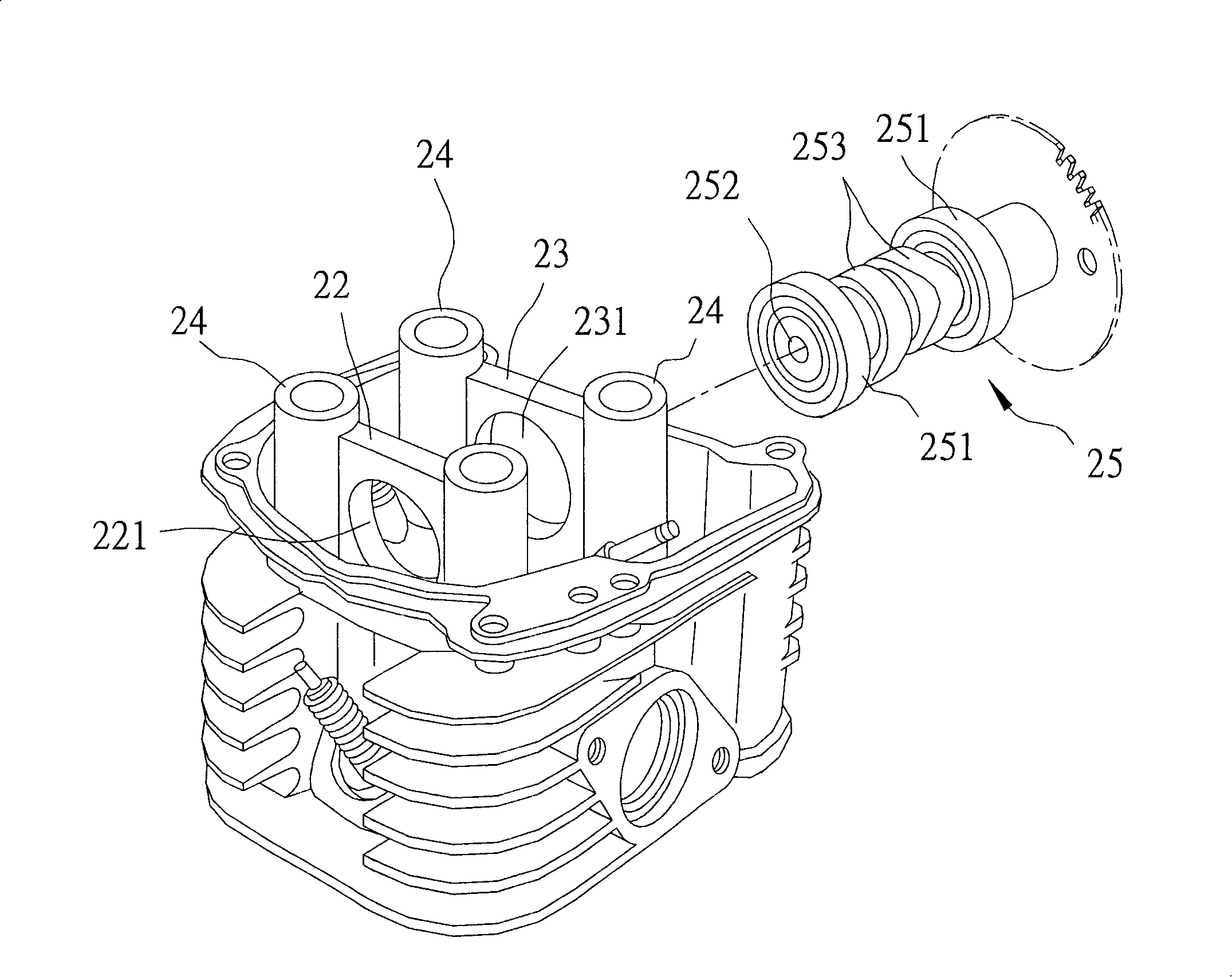
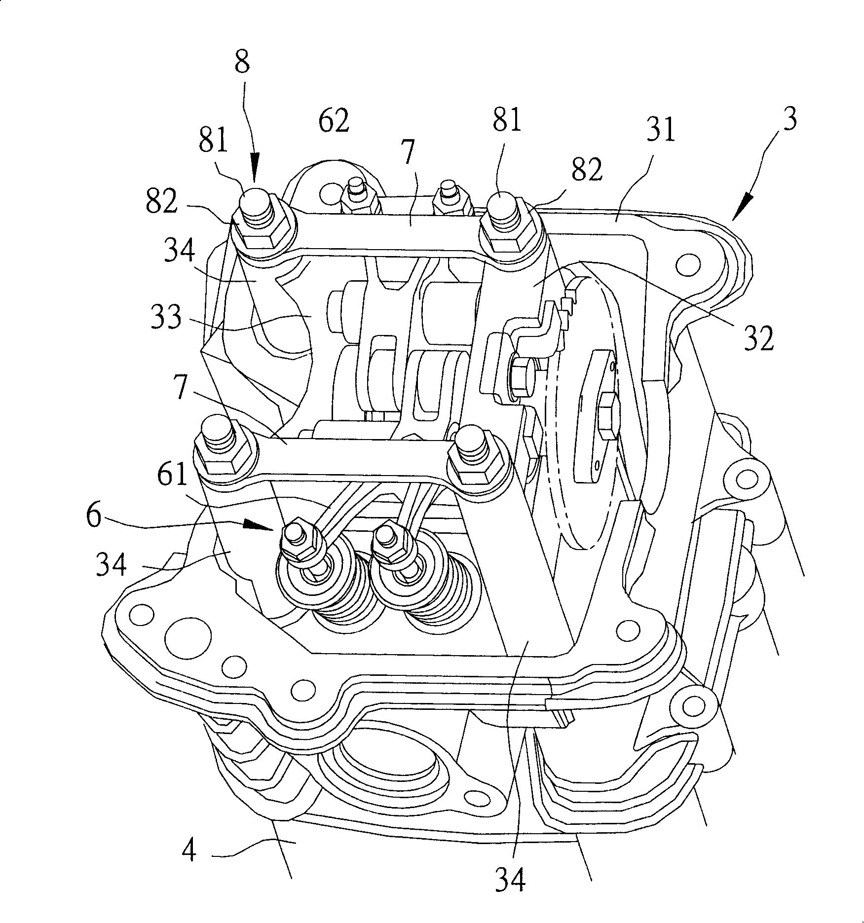
[0021] like image 3 , 4 As shown, the preferred embodiment of the cylinder head device with torsion bar of the present invention is installed on a cylinder block 4, and the cylinder head device includes a cylinder head 3, a camshaft group 5, a rocker arm unit 6, Two torsion bars 7, and a locking unit 8.
[0022] The cylinder head 3 is disposed on the cylinder block 4, and has a cylinder head body 31, a first support wall 32 and a second support wall 33 extending upwardly from the cylinder head body 31 at intervals, and four are respectively connected The first and second supporting walls 32 and 33 are provided with upright posts 34 on both sides. The first and second supporting walls 32 and 33 are formed with opposite mounting holes 321 and 331 , and each upright post 34 is formed with a screw hole 341 .
[0023] The camshaft group 5 is rotatably passed through the mounting holes 321 and 331 of the first and second supporting walls 32 and 33 to drive the rocker arm unit 6 to swing. In this preferred embodiment, the camshaft set 5 has two bearings 51 respectively disposed in the mounting holes 321 and 331 of the first and second supporting walls 32 and 33 , and a rotating shaft passing through the two bearings 51 . 52 , and two cams 53 disposed on the shaft 52 and between the two bearings 51 .
[0024] The rocker arm unit 6 is interposed between the first and second support walls 32 and 33 and can swing relative to the cylinder head 3 . In this preferred implementation, the rocker arm unit 6 has a first rocker arm 61 and a second rocker arm 62 pivotally connected to the first and second support walls 32 and 33 . The first and second rocker arms 61 , 62 are opposite. In this embodiment, the first and second rocker arms 61 and 62 are Y-shaped, and their bifurcated parts extend outwardly away from each other, and each outer end is connected to a valve rod 9 .
[0025] The orientations of the two cams 53 of the camshaft group 5 are different by a set angle, and the inner ends of the first and second rocker arms 61 and 62 are in contact with the two cams 53 respectively. The two cams 53 sequentially drive the first and second rocker arms 61 and 62 to swing up and down, whereby the linked valve rod 9 moves up and down sequentially to achieve the purpose of intake and exhaust.
[0026] The two torsion bars 7 are spaced apart from each other and are connected to the four uprights 34 on both sides of the first and second supporting walls 32 and 33 so as to form a horizontal and vertical alignment with the first and second supporting walls 32 and 33 . High rigidity structure with joints. In this preferred embodiment, a pair of through holes 71 corresponding to the screw holes 341 of the four uprights 34 are formed on both side ends of each torsion bar 7 .
[0027] The locking unit 8 has four bolts 81 respectively passing through the four through holes 71 of the two torsion bars 7 to be locked in the screw holes 341 of the four uprights 34 , and four bolts 81 correspondingly locked to the ends of the four bolts 81 to The two torsion bars 7 are pressed against the nuts 82 on the fourth column 34 of the cylinder head 3 .
[0028] The first and second support walls 32 and 33 of the cylinder head 3 are designed as one piece, and the two torsion bars 7 connecting the uprights 34 on both sides of the first and second support walls 32 and 33 can be used to make the cylinder head The structural rigidity of 3 is greatly improved, which not only allows the second bearing 51 of the camshaft group 5 to have better concentricity, but also maintains the required rigidity to resist the adverse effects caused by thermal deformation. Because of the high rigidity of the structure of the present invention, the gap between the first and second rocker arms 61, 62 and the first and second support walls 32, 33 can be limited, so as to avoid the output effect of the cylinder caused by the enlargement of the gap. reduce. In addition, the two torsion bars 7 can also replace the originally required spacers 162 (see figure 1 ) to reduce the number of components used.
[0029] To sum up the above, the cylinder head device with torsion bars of the present invention utilizes the two torsion bars 7 to connect the first and second support walls 32 and 33 to enhance the structural rigidity and resist the adverse effects caused by thermal deformation. And make the camshaft group 5 run more smoothly, so the purpose of the present invention can indeed be achieved.
[0030] The above descriptions are only preferred embodiments of the present invention, which cannot limit the scope of the present invention. That is, any simple equivalent changes and modifications made according to the scope of the patent application of the present invention and the contents of the description of the invention still belong to the present invention. covered by the patent.
[0031] 【Description of main component symbols】
[0032] 3 ………………Cylinder head 52………………Spindle
[0033] 31………………Cylinder head body 53…………Cam
[0034] 32………………First support wall 6 ………………Rocker arm unit
[0035] 321 ………………Mounting holes 61………………First rocker arm
[0036] 33………………Second support wall 62…………Second rocker arm
[0037]331 ………………Mounting holes 7 ………………Torsion bar
[0038] 34………………Column 71………………Perforated
[0039] 341 ………………Threaded holes 8 …………Locking unit
[0040] 4 ………………Cylinder block 81………………Bolts
[0041] 5 ……………Camshaft group 82………………Nuts
[0042] 51………………Bearing 9 ………… Valve stem

PUM

no PUM

Description & Claims & Application Information

We can also present the details of the Description, Claims and Application information to help users get a comprehensive understanding of the technical details of the patent, such as background art, summary of invention, brief description of drawings, description of embodiments, and other original content. On the other hand, users can also determine the specific scope of protection of the technology through the list of claims; as well as understand the changes in the life cycle of the technology with the presentation of the patent timeline. Login to view more.
Why Eureka
Try Eureka